Installation
26 S&C Instruction Sheet 716-500
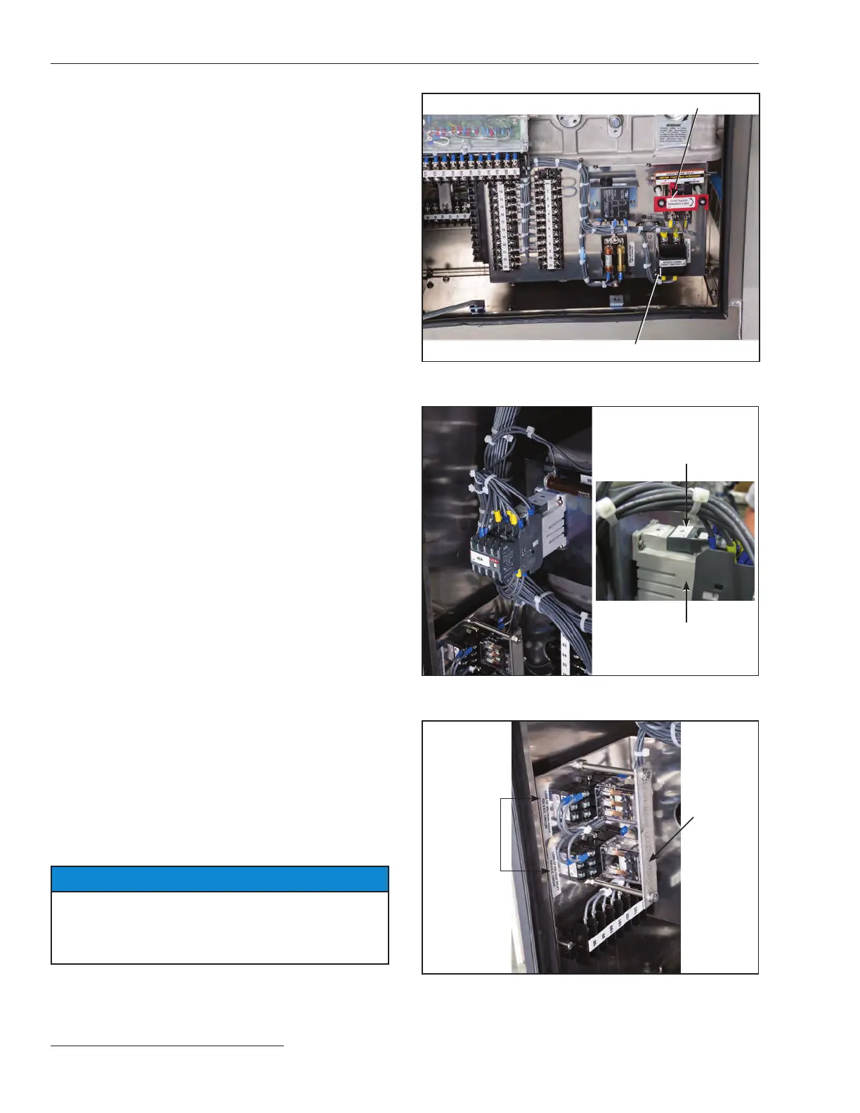
(d) In the switch operator make sure:
• Correct polarity has been observed on dc-control-
voltage models (see Figure 29)
• To check the motor contactor and surge suppres-
sor to ensure all electrical connections are secure,
and that the surge suppressor is fully-seated in its
mount (see Figure 30)
• Any optional “ice-cube” style relays (used for
catalog option “-P” and “-T2”) are fully seated in
their mounts (see Figure 31)
(e) Make sure all other pinned connections have been
made and all bolted connections have been securely
tightened.
STEP 24. Replace the access cover on the side of each
transition box and securely tighten the associated
5∕16-18 × ¾ hex-head stainless steel cap screws.
STEP 25. Replace the bottom plates, which were removed in
Step 7 on page 13, to the underside of the high-speed
base and securely tighten the associated ½-13 x 1¼
or ½-13 x 1¾ galvanized steel cap screws, at
washers, and nuts. See Figure 8 on page 13.
For circuit-switchers rated 161 kV and 230 kV:
Attach the six 13-inch x 3¼-inch adjustment plates
to the underside of the high-speed base. These
plates are used to cover small gaps between the
bottom plates, the operator support tube mounting
plate, and the mounting pedestal.
STEP 26. Insert the motor and closing circuit fuseholder, and
then close the control-source disconnect knife
switch. See Figure 29.
STEP 27. Press the CLOSE pushbutton or send a Close signal
to the switch operator. See Figure 23 on page 22.
The closing latch will release, discharging the
closing spring. This action closes the interrupters.
The switch-position indicator on the high-speed
base will move to the Closed position. Further, if
the position-indicating lamp option has been
specied, the red lamp will light.
STEP 28. When the circuit-switcher is ready to be placed in
service, the motor and closing circuit fuses can—at
the user’s option—be replaced with the slugs
furnished. This practice is recommended for
increased reliability because low-voltage fuses can
be damaged by the repeated inrush current
experienced during normal circuit-switcher
opening operations and can “sneak out,” leaving the
circuit-switcher inoperable.
NOTICE
Before replacing these fuses with slugs, make certain
that the control-source battery is adequately protected to
prevent discharge using fuses or circuit breakers located
at the battery bus.
STEP 29. Please complete and mail the circuit-switcher
registration card. The information requested on
this card is vital to ensure prompt notication in the
event eld modications are needed.
Knife switch
Motor and closing circuit fuse holder
Figure 29. Motor and closing circuit fuse holders. Control source
knife switch.
Surge suppressor out
of place.Push the surge
supressor (if present)
back into place.
Motor contactors and
auxiliary contactors should
be fully seated
Figure 30. Check the motor contactor and the surge suppressor
behind the operator side panel.
Optional
relays
Relay
retaining
plate
Figure 31. Check that all optional “ice-cube” style relays are fully
seated and that the retaining plate is in place.