10 S&C Instruction Sheet 663-500
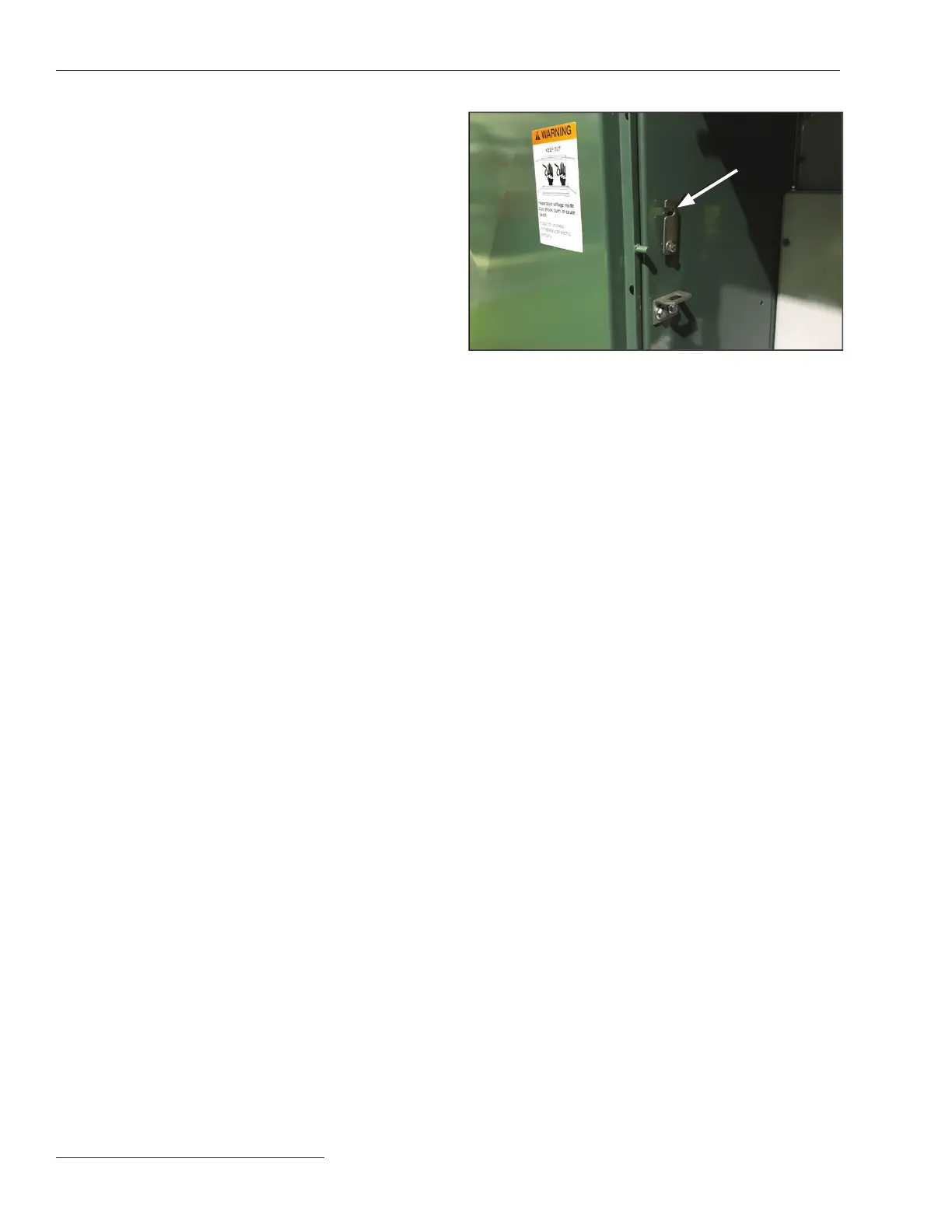
The left-hand door to the interior of the gear
is secured closed by a rotating latch and is
overlapped by the right-hand door, which is
equipped with the Penta-Latch Mechanism. The
left-hand door can be opened after opening the
right-hand door. Remove the tie wrap securing
it for shipment, and disengage the rotating latch
by rotating it upward. See Figure 4.
The left-hand door to the low-voltage control
compartment is secured closed by two captive
screws and is overlapped by the right-hand
door. This door can be opened after opening
the right-hand door and loosening the screws
securing it in place.
To close the doors: Close the left-hand door
and secure it as appropriate with the captive
screws or with the latch by rotating the latch
downward over the stop on the outer edge of the
door. See Figure 4. The right-hand door latches
automatically when the door is closed. To close a
door equipped with the Penta-Latch Mechanism,
place one hand at the midpoint of the door-front
near the edge and firmly push the door closed.
When the latch points are positively engaged,
the spring mechanism will trip to latch the door.
Pull outward on the cover of the Penta-Latch
Mechanism to verify the door has latched
securely. If it has not, use a pentahead (or hex-
head, when applicable) socket wrench or tool
to rotate the actuator counterclockwise until a
distinct click is heard and the actuator reaches
the stop. If the actuator will not rotate counter-
clockwise, the mechanism was already charged
for closing but was not closed properly. Close the
door again, making sure all latch points engage
completely and simultaneously. When the door
is securely latched, a padlock may be inserted
into the hasp.
Placement
STEP 2. At the installation site, remove all separately
packaged components shipped in the pad-
mounted gear enclosure and set them aside in a
protected area.
(a) Unbolt the enclosure from its skid and lift the
unit onto the mounting pad, observing the
precautions in the “Handling” section on page 8.
(b) Open the doors to the interior of the gear and
secure them with the door holders.
(c) Refer to the catalog dimensional drawing
furnished and verify the enclosure
compartments are positioned correctly and
the unit is properly aligned with respect to
the anchor bolts or ush anchors.
(d) If excess lengths of direct-buried cable are in
place and they must be fed into the enclosure
compartments as the unit is being lowered, the
doors must be opened (with door holders in
place) to allow any excess cable to feed over the
door stiles. If switch interphase and end barriers
(where applicable) are removed to facilitate this
procedure, note their position to ensure correct
reinstallation. It should not be necessary to
remove any upper barriers. Refer to Step 3 on
page 11 for instructions on removal of switch
barriers.
(e) Level the pad-mounted gear enclosure using
metal shims as required between the mounting
pad and the enclosure. Shim the enclosure until
the tops of the compartment doors are even.
Then, secure the enclosure to the pad using the
anchor brackets provided. See the anchor-bolt
detail on the catalog dimensional drawing. Make
sure all compartment doors open and latch
closed without binding. Binding indicates
enclosure distortion which must be corrected
with additional shimming.
Installation
Figure 4. Rotate the latch upward to disengage the left-hand
door, as shown above. To secure the left-hand door closed,
rotate the latch downward over the stop on the outer edge of
the door.
Door-latching
mechanism
disengaged
 Loading...


