S&C Instruction Sheet 663-500 15
Installation
WARNING
Low-voltage wiring routed inside the pad-mounted
gear enclosure must be a minimum of 6 inches
(152 mm) at 14.4 kV and 7½ inches (191 mm) at
25 kV away from components that will be energized
at high voltage. Do not place wiring where it might
fall onto a component that will be energized at high
voltage, such as the bus, or where it will be in the
way of moving parts.
Failure to maintain proper clearance can result in a
flashover, injury, and equipment damage.
NOTICE
Openings made into the low-voltage control
compartment must be sealed with a suitable
compound to prevent the entry of moisture or
animals. Failure to properly seal the openings can
result in damage to the electronic components.
NOTICE
Do not install the current sensors on unshielded
cables or on cables where the insulation is exposed
but ungrounded (for example, where dielectric tape
or heatshrink tubing is used). These current sensors
are intended for application at ground potential and
can be damaged by the voltage gradient between
the cable insulation and ground.
NOTICE
Twelve current sensors are required for source-
transfer pad-mounted gear furnished with optional
switch-terminal adapters (catalog number suffix
“-M1”) that permit two cables per phase. Install
the current sensors in accordance with the wiring
diagram provided.
The automatic source-transfer scheme will not
operate properly when only six current sensors are
installed.
S&C Current Sensors
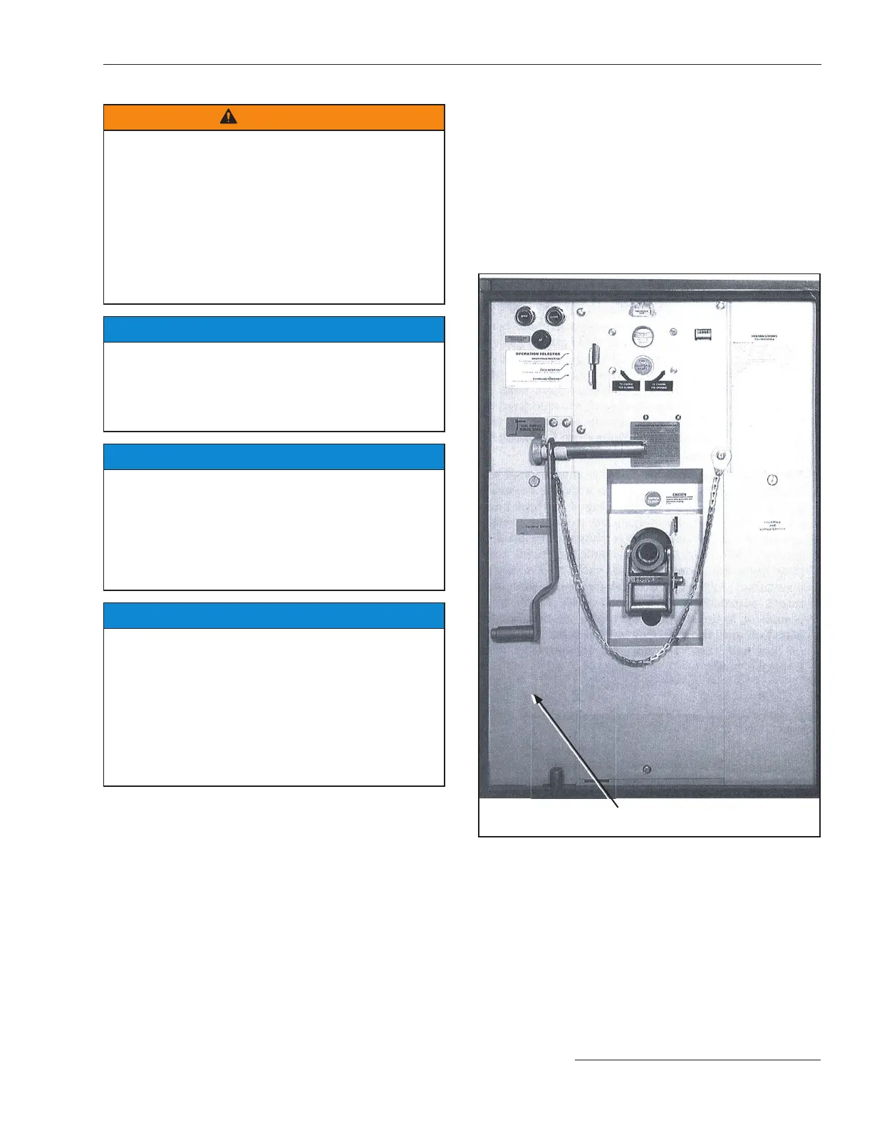
STEP 7. Six S&C Current Sensors (packed separately)
are provided for units furnished with the
optional Overcurrent Lockout feature
(catalog number suf x “-Y2”). The leads from
the current sensors in each switch compartment
must be connected to a terminal block located
in the associated terminal-block compartment,
behind the bolted panel labeled “Terminal
Blocks.” See Figure 9.
The bottom plate in each terminal-block
compartment is removable to facilitate drill-
ing an entrance hole for the lead wires. When
conduit is not used, protect the lead wires from
abrasion against the knockout opening with
a rubber grommet or by taping. Then, apply a
suitable compound to fill the space between the
lead wires and the opening to prevent entry of
moisture or animals.
Figure 9. The left side of the low-voltage control compartment
showing the left terminal-block compartment (the right
terminal-block compartment is similar) for connection of
leads from S&C Current Sensors furnished with the optional
Overcurrent Lockout feature (option suffix “-Y2”); and for
customer connections when optional auxiliary switches (suffix
“-C9” or “C10”), the Remote Indication feature (option suffix
“-Y4”), or the Supervisory Control feature (option suffix “-Y6”)
is furnished. Terminal blocks for options “-Y4” and “-Y6” are in
the left terminal-block compartment only.
Termination-block
compartment
 Loading...


