S&C Instruction Sheet 662-505 9
Installation
Placement
STEP 3. At the installation site, remove all separately
packaged components shipped in the pad-
mounted gear enclosure and set them aside in a
protected area.
(a) Unbolt the enclosure from its skid and lift the
unit onto the mounting pad, observing the
precautions given in the “Handling” section
on page 5.
(b) Open the doors to the interior of the gear and
secure them with the door holders. Refer to
the catalog dimensional drawing furnished
and verify the enclosure compartments are
positioned correctly and the unit is properly
aligned with respect to the anchor bolts (or
ush anchors).
(c) If excess lengths of direct-buried cable are in
place and it is desired to feed them into the
enclosure compartments as the unit is being
lowered, the doors must be opened (with
door holders in place) to allow any excess
cable to be fed over the door stiles.
(d) If switch interphase and end barriers (where
applicable) are removed to facilitate this
procedure, note their positioning to ensure
correct reinstallation later.
It should not be necessary to remove any
upper barriers. Refer to Step 4 in the “Cable
Terminations” section on page 10 for
instructions for removal of switch barriers.
(e) Level the pad-mounted gear enclosure using
metal shims as required between the
mounting pad and the enclosure.
(f) Shim the enclosure of four-compartment
units until the tops of the compartment
doors are even.
(g) For two-compartment units, shim the
enclosure until the top of each door is
parallel with the top of the gear.
(h) Secure the enclosure to the pad using the
anchor brackets provided (see anchor-bolt
detail on the catalog dimensional drawing).
Make sure all compartment doors open and
latch closed without binding. Binding
indicates enclosure distortion which must
be corrected by additional shimming.
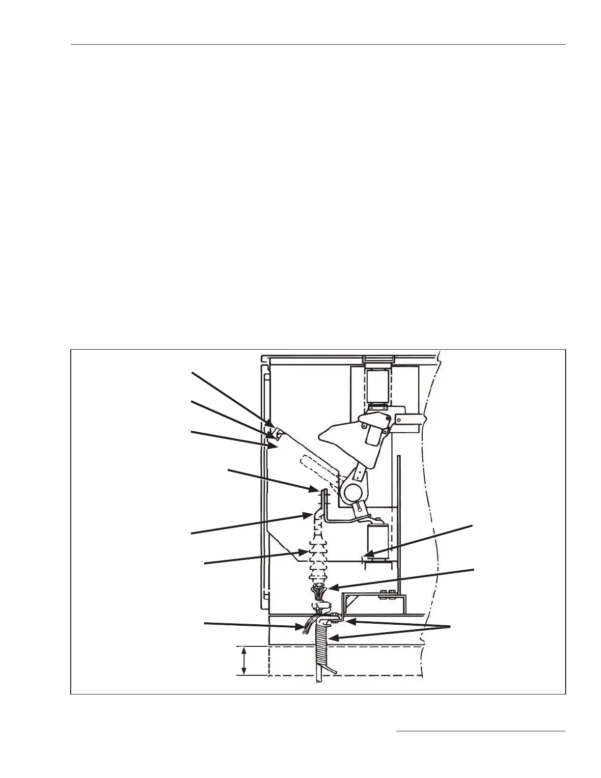
Figure 5. Side view of the switch showing the interphase barrier attachment points, terminal-pad connections, and optional cable
guides.
Mounting angle and cable-
support bracket (furnished
with catalog number suffix
“-M2,” catalog number suffix
“-M3” is similar)
Barrier guide
Concentric-neutral
ground wires
Barrier-support angle
Wing-head screw
Switch interphase barrier
Connect terminator (or connector)
to two uppermost holes on switch
terminal pad when catalog number
suffix “-M2” is specified
Offset spade-type
compression terminal
Cable terminator
To Ground Bus
12-inch (30-cm) min. base spacer
or cable pit (required if catalog
number suffix “-M2” or “-M3” is
specified)
Connect terminator (or connector)
Switch interphase barrier
Switch interphase barrier
 Loading...


