EasyManua.ls Logo

Sanremo verona sap User Manual

Sanremo verona sap
26 pages
To Next Page IconTo Next Page
Page #1 background imageLoading...
Page #1 background image
50
ENGLISH
VERONA
FOREWORD



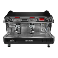
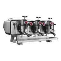
This booklet refers to the following models:
Model – VERONA SAP

2 - 3 group versions
Model – VERONA SED - SED TCS

2 -3 group versions
SPECIFICATIONS
GROUPS 2 BASE 2 TCS 2 BASE TALL 2 TCS TALL 3 BASE 3 TCS 3 BASE TALL 3TCS TALL
Width (X) mm 820 820 820 820 1050 1050 1050 1050
Depth (Y) mm 610 610 610 610 610 610 610 610
Height (Z) mm 590 590 652 652 590 590 652 652
Boiler capacity litres 12 8,6 12 8,6 19 14 19 14
Small boiler capacity litres / 0,28 / 0,28 / 0,28 / 0,33
Net weight Kg 59 60 63 64 84,5 85,5 92 92
Gross weight Kg 62 63 66 67 89,5 90,5 99 99
Supply voltage V
120
220 - 240
380 - 415
120
220 - 240
380 - 415
120
220 - 240
380 - 415
120
220 - 240
380 - 415
120
220 - 240
380 - 415
120
220 - 240
380 - 415
120
220 - 240
380 - 415
120
220 - 240
380 - 415
Power absorbed by the boiler resistance kW 2,7/4,5 2,7/4,5 2,7/4,5 2,7/4,5 5,1 5,1 5,1 2,7
Power absorbed by the tcs small boiler resistance
kW / 1 / 1 / 1 / 1
Power absorbed by cup warmer kW 0,2 0,2 0,2 0,2 0,25 0,25 0,25 0,25
Power absorbed by the electric pump kW 0,15/0,165 0,15/0,165 0,15/0,165 0,15/0,165 0,15/0,165 0,165 0,15/0,165 0,165
Power absorbed by the solenoid valves kW 0,15/0,165 0,15/0,165 0,15/0,165 0,15/0,165 0,15/0,165 0,187 0,15/0,165 0,187
Power absorbed by the external electric pump kW 0,0225 0,0225 0,0225 0,0225 0,0315 0,0315 0,0315 0,0315
Power absorbed by the automatic level regulator
kW 0,01 0,01 0,01 0,01 0,01 0,01 0,01 0,01
Boiler project pressure (2 Bar) MPa 0,2 0,2 0,2 0,2 0,2 0,2 0,2 0,2
Boiler working pressure (0,8-1 Bar) MPa 0,08:0,1 0,08:0,1 0,08:0,1 0,08:0,1 0,08:0,1 0,08:0,1 0,08:0,1 0,08:0,1
Safety valve calibration pressure (1,8 Bar) MPa 0,18 0,18 0,18 0,18 0,18 0,18 0,18 0,18
Heat exchanger project pressure (20 Bar) MPa 2 2 2 2 2 2 2 2
Heat exchanger safety valve calibration
pressure
(12 Bar) MPa 1,2 1,2 1,2 1,2 1,2 1,2 1,2 1,2
Water mains pressure (max) (6 Bar) MPa 0,6 0,6 0,6 0,6 0,6 0,6 0,6 0,6
Coffee distribution pressure (8-9 Bar) MPa 0,8/0,9 0,8/0,9 0,8/0,9 0,8/0,9 0,8/0,9 0,8/0,9 0,8/0,9 0,8/0,9
The weighted sound pressure level A of the coffee machine is less than 70dB.


Y
Z
X

Other manuals for Sanremo verona sap

Question and Answer IconNeed help?

Do you have a question about the Sanremo verona sap and is the answer not in the manual?

Sanremo verona sap Specifications

General IconGeneral
BrandSanremo
Modelverona sap
CategoryCoffee Maker
LanguageEnglish

Summary

Foreword

Specifications

Installation

Electrical Connection

Instructions for connecting the power cable and safety switch.

Installing the Power Supply Cable

Guidance on connecting the power supply cable to the appliance.

Water Connection

Use

Operational Checks and Dispensing

Covers preliminary checks, hot water, steam, and coffee dispensing procedures.

Dispenser Programming

Cleaning

Warnings and Information

Appliance Failure

Troubleshooting steps and contact information for appliance failures.

Warranty

Details regarding the appliance's warranty coverage and limitations.

Information for Users

Information regarding product disposal and environmental regulations.

Warning – Correct Use of Rotary Pumps

Programming of the 3DS Maestro De Lux Control Unit

User Interface

Overview of buttons, LEDs, and display elements for user interaction.

Inputs / Outputs

Description of the appliance's input and output connections.

Switching on the Doser

Idle On Status (On)

Describes the doser's status when powered but not actively dispensing.

Distribution

Coffee Cycle

Detailed steps for performing a coffee distribution cycle.

Stop Coffee Distribution in Progress

Procedure to interrupt an ongoing coffee distribution.

Distribution

Pre-Brewing

Explanation of the pre-brewing function for coffee dispensing.

Coffee Distribution in Continuous Mode

Instructions for continuous coffee dispensing.

Tea Cycle Distribution

Procedure for dispensing tea, including stopping the cycle.

Level Management and Regulation

Minimum Level Probe

Details on the minimum level probe function and its role in boiler filling.

Level Management and Regulation

Probe and Function Settings

Covers chrono function, disabling temperature display, and probe settings.

Washing Cycles

Procedures for group washing and steam wand washing.

Level Probe

Characteristics and Heating

Describes probe characteristics, coffee boiler heating, and regulating modes.

Regulating Modes

Thermoregulation Modes

Explains ON/OFF regulation with hysteresis and PID regulation.

Programming and Readings

Programming Coffee Doses

Procedure for modifying and memorizing volumetric coffee dose quantities.

Programming Continuous/3coffees Dose

Instructions for programming continuous or 3-coffee doses.

Programming Tea Doses

Programming Steam Temperature by Simulation

Programming the Clock

Auto On/Off - Automatic Switching On/Off

Rest Day

Reading Consumption, Litres, Maintenance

Technical Level Programming

Basic Settings

Covers language, user name, and service phone number settings.

Function Crono

Setting for the chrono function to display coffee distribution time.

Technical Level Programming

Keyboard Type

Selection of the keyboard type used on the doser.

Function Settings

Enabling/disabling specific functions like dose programming and continuous dose.

Technical Level Programming

Cleaning

Setting the duration for steam wand washing.

Pre-Brewing and Probe Sensitivity

Configuration of pre-brewing times and probe sensitivity levels.

Service Cycles and Temperature Settings

Setting service cycles and display temperature units (Celsius/Fahrenheit).

PID Thermoregulation

Parameters for proportional, integrative, and derivative control.

Technical Level Programming

PID Thermoregulation Parameters

Detailed parameters for PID control, including range and constants.

Filling Up T-Out

Setting the time-out for the boiler filling phase.

Water Filter

Parameter for setting the water filter's capacity in litres.

Alarm Signal

Time Out Level in Boiler (Filling)

Indicates an alarm when boiler filling exceeds the set time-out.

Boiler Temperature Probe Shortcircuiting/Excess Temperature

Alarm for probe issues or exceeding temperature limits.

Absence of Impulses of the Flow Meter (5 Seconds)

Alarm triggered by missing flow meter impulses for a set duration.

Filter Alarm and Reset

Signal for filter replacement and procedure to reset the count.

Alarm Signal

Maintenance Alarm and Reset

Resetting maintenance alarms related to service cycles.

Reset Total Single Doses

Procedure to reset the consumption count of single doses.

Preset Default Data

Procedures in the Event of a Power Cut

Programming the PIDBULL Control Unit

Group Identification

Identifies groups and displays software version.

System Status Modes

Describes OFF, IDLE ON, and Group Switching Off statuses.

Programming T°SET

Procedure to set the desired boiler temperature (T°SET).

Programming the PIDBULL Control Unit

Switching Off a Single Group

How to switch off individual groups to avoid alarms.

PID Thermoregulation

Explanation of PID control algorithm and constants (P, i, d).

Temperature Offset

Function to adjust displayed temperature based on physical heat loss.

Technical Level Programming

Accessing and setting technical parameters.

Technical Level Programming

F.01 = Number of Heating Groups

Setting the number of usable heating groups (1, 2, or 3).

F.02 = Number of Keyboards

Setting the number of keyboards connected to the system.

F.03 = Degrees Celsius or Degrees Fahrenheit

Setting the temperature display unit to Celsius or Fahrenheit.

PID and Offset Settings

Configuration of PID constants and group temperature offsets.

Alarm Signal

Temperature Probe Unconnected / Interrupted

Alarm indication for issues with the boiler temperature probe.

Temperature Probe Shortcircuiting / Excess Temperature

Alarm for short-circuited or excessively high probe temperatures.

Preset Default Data

Procedures in the Event of a Power Cut

Related product manuals