Do you have a question about the Sansui AU-20000 and is the answer not in the manual?
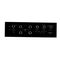
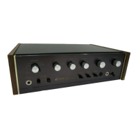
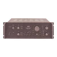
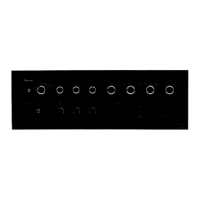
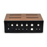
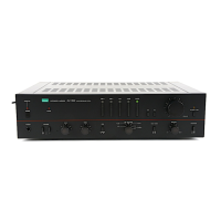
Identifies the specific model and type of audio equipment.
Procedure for adjusting critical driver circuits for optimal performance.
Steps for calibrating the amplifier's power output meters.
Identifies issues and causes related to the unit's power supply.
Pinpoints problems and solutions for the main amplification stage.
Addresses problems related to incorrect bias current settings.
Lists causes and symptoms for power meter malfunctions.
Details issues and fixes for the speaker protection system.
Guides users through diagnosing and resolving pre-amplifier circuit problems.
Lists components and their locations on the input circuit board.
Details parts and placement for the tape copy circuit.
Provides component details for the equalizer circuit board.
Lists parts and locations for the main volume control circuit.
Details components and their positions on the flat amplifier board.
Lists parts and locations for the tone control circuit board.
Provides component details for the tone amplifier circuit board.
Lists parts and locations for the meter circuit board.
Details components and their positions on the filter circuit board.
Lists parts and locations for the driver circuit board.
Provides component details for the protector circuit board.
Details components and their positions on the filter amplifier board.
Lists parts and locations for the regulated power supply board.
Details components and their positions on the connector circuit board.
Lists parts and locations for another connector circuit board.
Reference list of semiconductor components used in the unit.
Visual guide to various connector and pin assembly types.
Instructions for selecting the correct AC input voltage.
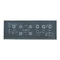
Listing of front-side mechanical and control components.
List of miscellaneous internal and external parts.
Detailed schematic for the pre-amplifier circuitry.
Detailed schematic for the power amplifier circuitry.
| Total Harmonic Distortion | 0.05% |
|---|---|
| Input Sensitivity | 2.5mV (MM), 150mV (line) |
| Output | 150mV (line) |
| Speaker Load Impedance | 4Ω to 16Ω |
| Power Output | 170 W per channel into 8Ω (stereo) |
| Frequency Response | 5Hz to 50kHz |
| Signal to Noise Ratio | 75dB (MM), 90dB (line) |
| Channel Separation | 60dB (line) |