Do you have a question about the Sansui AU-517 and is the answer not in the manual?
| Damping Factor | 80 |
|---|---|
| Input Sensitivity | 2.5mV (MM) |
| Signal to Noise Ratio | Phono MM: 75dB, Line: 100dB |
| Speaker Load Impedance | 8 ohms |
| Dimensions | 430 x 150 x 360 mm (W x H x D) |
| Channel Separation | 60dB |
| Power Output | 65W + 65W (8 ohms, 20Hz-20kHz) |
Details on amplifier output power, distortion, frequency response, and impedance characteristics.
Specifications for input signal levels, impedance, and channel separation.
Information on tone controls, filters, loudness, power requirements, dimensions, and weight.
High-level functional blocks showing signal flow and component interconnections for both models.
Explains design benefits like phase response, FET usage, push-pull drivers, and phase advancer circuits.
Describes the operation of the differential amplification stages and the final output stage.
Procedures for setting DC offset voltage and bias current on the driver boards.
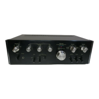
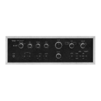
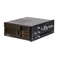
Identifies key components and their locations on the top of the chassis for both models.
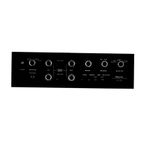
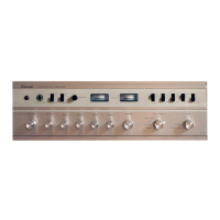
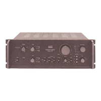
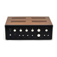
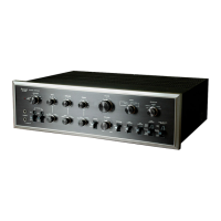
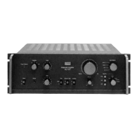
Identifies front panel components and their locations.
Part layout and list for the input terminal circuit board.
Part layout and list for the equalizer circuit board.
Part layout and list for the tone control circuit board.
Part layout and list for the bass and treble volume circuit board.
Part layout and list for the pre-main switch circuit board.
Part layout and list for the tape play circuit board.
Part layout and list for the F-2720 tone control circuit board.
Part layout and list for the F-2665 bass and treble volume circuit board.
Part layout and list for the F-2666 turn over switch circuit board.
Part layout and list for the L-CH driver circuit board.
Part layout and list for the R-CH driver circuit board.
Part layout and list for the power supply and protector circuit board.
Schematic diagram for the AU-517 power supply section.
Schematic diagram for the AU-717 power supply section.
Explains how the circuit protects speakers from DC voltage.
Details the circuit's protection mechanism against excessive current.
Describes the operation of the astable multivibrator for the protector indicator LED.
Lists the materials used for packing the main unit.
Lists the accessories included with the product.