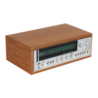
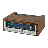
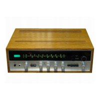
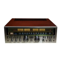
Do you have a question about the Sansui eight-deluxe and is the answer not in the manual?
Detailed specifications for the audio output power, sensitivity, and distortion characteristics.
Technical specifications for FM and AM tuning range, sensitivity, selectivity, and response.
Specifications for semiconductors, power requirements, dimensions, and weight.
Visual representation of the unit's internal circuitry and signal flow between modules.
Graphical illustration of signal levels at various points within the audio signal path.
Procedure for setting DC zero volts and bias current on the driver circuit board.
Steps for aligning the FM Intermediate Frequency circuit for optimal performance.
Procedure for calibrating the FM dial scale and aligning RF circuits.
Steps for adjusting FM signal meter, distortion, tune meter, and muting functions.
Procedure for aligning the Multiplex (MPX) circuit for stereo signal processing.
Steps for aligning AM IF, dial calibration, RF, and signal meter circuits.
Instructions for threading the dial cord for the pointer mechanism.
Instructions for threading the dial cord for the variable capacitor mechanism.
Procedure for attaching and setting the dial pointer correctly.
Guide for diagnosing and resolving power supply related issues.
Steps for identifying and fixing problems within the audio circuits.
Troubleshooting steps for when the AUX input is not functioning.
Guide for diagnosing and resolving issues with the PHONO input.
Troubleshooting steps for when the FM reception is not working.
Steps to troubleshoot issues with the FM muting circuit.
Guide for fixing problems with FM stereo channel separation.
Troubleshooting steps for when the AM reception is not working.
Component layout and parts list for the FM IF circuit board.
Component layout and parts list for the FM MPX circuit board.
Component layout and parts list for the AM circuit board.
List and location of various components found on the top side of the unit.
List and location of various components found on the bottom side of the unit.
Procedure for adjusting the unit's voltage selector for different power sources.
Instructions for removing and replacing the tuner section components.
| Power Output | 60 watts per channel into 8Ω (stereo) |
|---|---|
| Total Harmonic Distortion | 0.3% (at rated power) |
| Input Sensitivity (phono) | 2.5mV |
| Input Sensitivity (line) | 150mV |
| Signal to noise ratio | 70dB (MM), 80dB (line) |
| Tuning Range (FM) | 87.5-108MHz |
| Tuning Range (AM) | 530-1605kHz |
| Speaker Impedance | 4 to 16Ω |
| Channel separation | 50dB |