Do you have a question about the Sansui G-3000 and is the answer not in the manual?
Technical details of the audio output stage, including power, distortion, and frequency response.
Technical specifications for the FM tuner, covering sensitivity, selectivity, and distortion.
Technical specifications for the AM tuner, detailing sensitivity, selectivity, and signal-to-noise.
Explains the circuit that prevents loud pops from speakers when powering the unit on or off.
Procedures for calibrating the FM tuner, including IF coils, dial, and signal meter.
Specific steps for adjusting the IF stage and tuning dial for FM reception.
Steps to adjust the PLL VCO and stereo separation for optimal FM stereo reception.
Procedures for calibrating AM IF coils, dial, and RF stages.
Instructions for setting the bias current of the power amplifier transistors.
Component layout and parts list for the tuner section's circuit board.
Component layout and parts list for the pre/main amplifier and power supply board.
Provides component layouts and parts for various specific circuit boards.
Guide for safely removing the square-shaped control knobs from the front panel.
Instructions for replacing the tuning dial and signal strength meters.
Steps for removing and installing the main volume control potentiometer.
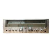
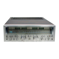
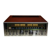
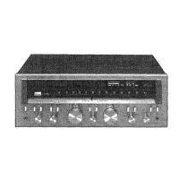
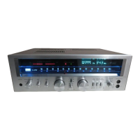
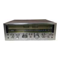
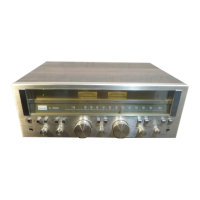
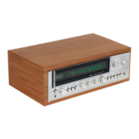
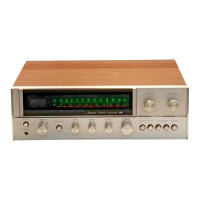
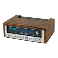
Visual guide identifying various external and internal components shown in front and top views.
Detailed instructions for replacing the dial cord and attaching the dial pointer.
| Power Output | 30 watts per channel (8 ohms, 20Hz-20kHz) |
|---|---|
| Total Harmonic Distortion | 0.1% |
| Input Sensitivity | 2.5mV (MM), 150mV (line) |
| Tuning Range | FM: 87.5 - 108 MHz, AM: 530 - 1600 kHz |
| Speaker Load Impedance | 8 ohms |