EasyManua.ls Logo

Sanyo C2432A - User Manual

Sanyo C2432A
50 pages
To Next Page IconTo Next Page
Loading...
1
S4359249
INSTALLATION INSTRUCTIONS
SANYO FISHER COMPANY
A DIVISION OF SANYO NORTH
AMERICA CORPORATION
21605 Plummer Street
Chatsworth, CA91311
IMPORTANT Page
Please Read Before Starting .................................. 2
1. GENERAL ............................................................. 3
1-1. Tools Required for Installation (not supplied)
1-2. Accessories Supplied with Unit
1-3. Optional Copper Tubing Kit
1-4. Type of Copper Tube and Insulation Material
1-5. Additional Materials Required for Installation
1-6. Operating Range
1-7. Tubing Length
2. SELECTING THE INSTALLATION SITE ............ 7
Indoor Unit
Outdoor Unit
2-1. Air Discharge Chamber for Top Discharge
2-2. Wind Shield for “CL” Model
3. HOW TO INSTALL THE INDOOR UNIT ............ 10
Recessed Type (XS Type) ................................ 10
3-1. Suspending the Indoor Unit
3-2. Preparation for Suspending
3-3. Placing the Unit Inside the Ceiling
3-4. Installing the Drain Piping
3-5. Checking the Drainage
3-6. Before Installing the Ceiling Panel
3-7. Installing the Ceiling Panel
3-8. When Removing the Ceiling Panel for
Servicing
3-9. Duct for Fresh Air
Ceiling-Mounted Type (TS Type)..................... 18
3-10. Suspending the Indoor Unit
3-11. Duct for Fresh Air
3-12. Installing the Drain Piping
Wall-Mounted Type (KS Type) ........................ 22
3-13. Removing the Wall Fixture from the Unit
3-14. Selecting and Making a Hole
3-15. Installing the Wall Fixture onto Wooden or
Gypsum Wall
3-16.
Removing the Casing to Install the Indoor Unit
3-17. Removing the Grille to install the Indoor Unit
3-18. Preparing the Indoor Side Tubing
3-19. Wiring Instructions
3-20. Wiring Instructions for Inter-Unit Connections
3-21. Shaping the Tubing
3-22. Installing the Drain Hose
4. HOW TO INSTALL THE REMOTE
CONTROL UNIT ................................................. 33
Wireless Remote Control Unit
4-1. Mounting on a Wall (except KS2432A)
4-2. Mounting on a Wall (KS2432A only)
Wired Remote Control Unit (Option) (except 2432A)
4-3. Installing the Wired Remote Control Unit
CONTENTS
— Split System Air Conditioner —
85464359249001
5. ADDRESS SWITCHES (except KS2432A) ....... 36
5-1. Finding the Address Switches
5-2. Switch Positions for 2 Units or 2 Groups of
Units
6. HOW TO INSTALL THE OUTDOOR UNIT ........ 37
6-1. Removing the Protective Spacer for
Transportation
6-2. Installing the Outdoor Unit
6-3. Tubing Direction
7. ELECTRICAL WIRING ....................................... 38
7-1. General Precautions on Wiring
7-2. Recommended Wire Length and Wire
Diameter for Power Supply System
7-3. Wiring System Diagram
7-4. Examples of Incorrect Wiring
7-5. How to Connect Wiring to the Terminal
8. HOW TO PROCESS TUBING ........................... 41
8-1. Use of the Flaring Method
8-2. Flaring Procedure with a Flare Tool
8-3. Precaution before Connecting Tubes Tightly
8-4. Precautions during Brazing
8-5. Connecting Tubing between Indoor and
Outdoor Units
8-6. Insulating the Refrigerant Tubing
8-7. Taping the Tubes
8-8. Finishing the Installation
9. AIR PURGING .................................................... 44
Air Purging with a Vacuum Pump
(for Test Run)
10.TEST RUN .......................................................... 47
10-1. Preparing for Test Run
10-2. Performing Test Run
10-3. Performing Test Run with Optional Wired
Remote Control Unit
Basic Functions of the Service Valves
Pump Down
Units should be installed by licensed contractor
according to local code requirements
Model Combinations
Combine indoor and outdoor units only as listed below.
Indoor units Outdoor units
XS2432 (PNR-XS2432) C2432A
TS2432 CL2432A
KS2432
KS2432A
KS3032 C3032A
CL3032A
XS3632 (PNR-XS3632) C3632A
TS3632 CL3632A
KS3632
XS4232 (PNR-XS3632) C4232A
TS4232 CL4232A
Power Supply: 60Hz, single-phase, 208/230 V

Table of Contents

Question and Answer IconNeed help?

Do you have a question about the Sanyo C2432A and is the answer not in the manual?

Sanyo C2432A Specifications

General IconGeneral
TypeSplit System
Cooling Capacity24000 BTU
Power Supply220V, 50Hz
Operating Temperature (Cooling)18°C to 43°C
Noise Level (Indoor)45 dB

Summary

Important Safety and Precautions

When Installing

Guidelines and precautions for installing the air conditioner unit safely.

When Wiring

Critical safety warnings and procedures for electrical wiring.

When Servicing

Safety measures to follow when performing maintenance or repairs.

Health and Environmental Precautions

Warnings regarding toxic gas production and ventilation requirements.

General Information and Specifications

1-1. Tools Required for Installation

Lists the tools that are not supplied with the unit but are necessary for installation.

1-2. Supplied Accessories

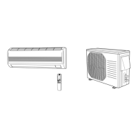
Details the accessories included with the air conditioning unit.

1-4. Copper Tube and Insulation Material

Specifies the type and thickness of copper tubes and insulation required.

1-6. Operating Range

Defines the temperature limits for indoor and outdoor unit operation.

Installation Site Selection

Indoor Unit Installation Site

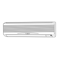
Guidelines on suitable and unsuitable locations for the indoor unit.

Outdoor Unit Installation Site

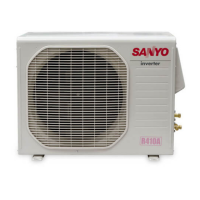
Recommendations for placing the outdoor unit for optimal performance and longevity.

Indoor Unit Installation: Recessed Type

3-1. Suspending the Recessed Indoor Unit

Instructions for securely suspending the recessed indoor unit from the ceiling.

3-3. Placing the Unit Inside the Ceiling

Steps for positioning the indoor unit within the ceiling space.

3-4. Installing the Drain Piping

Guidance on connecting and routing the drain pipe for condensate removal.

3-5. Checking the Drainage

Procedure to verify that the water drains smoothly and without leaks.

3-6. Ceiling Panel Preparation and Installation

Steps for preparing and attaching the ceiling panel to the unit.

3-9. Duct for Fresh Air

Instructions for connecting the duct for drawing in fresh outdoor air.

Indoor Unit Installation: Ceiling-Mounted Type

3-10. Suspending the Ceiling-Mounted Unit

Method for securely hanging the ceiling-mounted indoor unit.

3-12. Installing the Drain Piping

Procedure for connecting the drain pipe for ceiling-mounted units.

Indoor Unit Installation: Wall-Mounted Type

3-13. Removing Wall Fixture from Unit

Steps to detach the wall fixture from the indoor unit.

3-14. Selecting and Making Wall Hole

Guidance on choosing the location and drilling the hole for tubing.

3-15. Installing the Wall Fixture

Instructions for attaching the wall fixture securely to the wall.

Indoor Unit Casing and Tubing Preparation

3-16. Removing the Indoor Unit Casing

Procedure for removing the casing of the indoor unit for access.

3-17. Removing the Grille

Steps to remove the air intake grille for internal access.

3-18. Preparing Indoor Side Tubing

Routing and preparing refrigerant tubing from the indoor unit.

Wiring and Tubing Connections

3-19. Wiring Instructions

General precautions and guidelines for electrical wiring.

3-20. Inter-Unit Wiring Connections

Instructions for connecting wiring between indoor and outdoor units.

3-21. Shaping the Tubing

Techniques for bending and shaping refrigerant tubing for routing.

Drain Hose and Remote Control Installation

3-22. Installing the Drain Hose

Procedure for properly installing the drain hose for condensate.

4. Remote Control Unit Installation

General guidelines for installing the wireless remote control unit.

4-2. Wireless Remote Installation for KS2432 A

Specific steps for installing the wireless remote on KS2432A model.

Wired Remote Control Unit Installation

Instructions for installing the optional wired remote control unit.

System Setup and Configuration

5. Address Switches (except KS2432 A)

Setting address switches for proper unit operation and control.

6. Outdoor Unit Installation

Steps for correctly installing and securing the outdoor unit.

Electrical Wiring Procedures

7-1. General Precautions on Wiring

Essential safety rules and precautions before starting electrical wiring.

7-5. Connecting Wiring to the Terminal

Detailed instructions on how to connect wires to unit terminals.

Tubing Processing and Insulation

8-2. Flaring Procedure with a Flare Tool

Step-by-step guide for creating flares on copper tubing ends.

8-5. Connecting Tubing between Indoor and Outdoor Units

Instructions for securely connecting the refrigerant tubing between units.

8-6. Insulating the Refrigerant Tubing

Applying insulation to refrigerant tubing to prevent condensation.

Air Purging and Leak Testing

9. Air Purging

Explanation of why air purging is necessary for the refrigerant system.

Leak Test and Evacuation

Procedures for performing leak tests and evacuating the system.

Charging Additional Refrigerant

Instructions for charging the system with the correct amount of refrigerant.

Test Run Procedures

10-1. Preparing for Test Run

Pre-operation checks to ensure readiness for the test run.

10-2. Performing Test Run

Steps for conducting the initial test run of the air conditioner.

10-3. Test Run with Optional Wired Remote

Procedure for performing a test run using the optional wired remote control.

Service Valve Functions and Pump Down

Basic Functions of the Service Valves

Explanation of the operation and function of service valves.

Pump Down Procedure

Steps for recovering refrigerant gas into the outdoor unit.

Related product manuals