10 S4359249
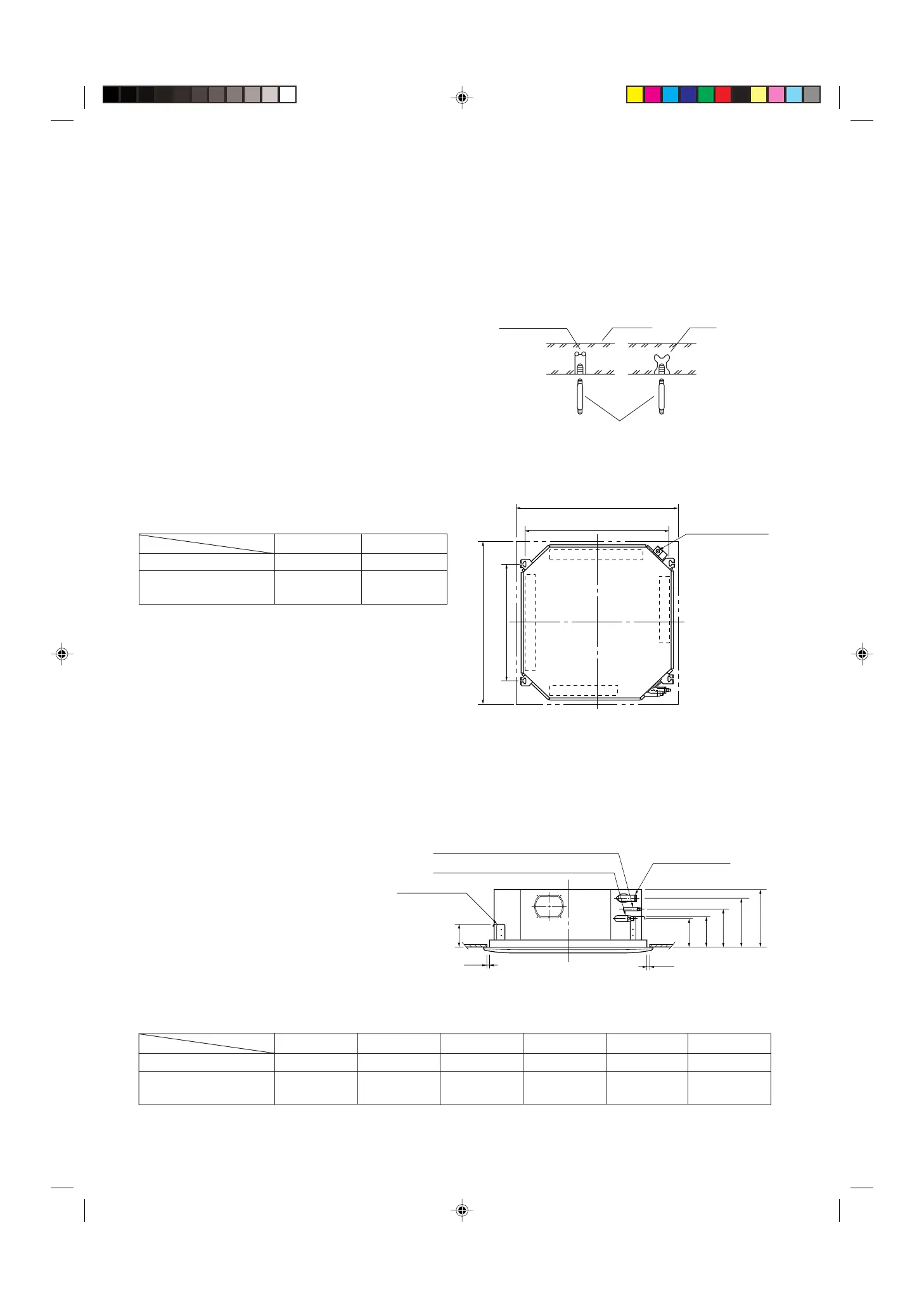
Fig. 3-1
Hole-in-anchor
Hole-in-plug
Concrete Insert
Suspension bolt (M10 or 3/8")
(field supply)
0038_T_I
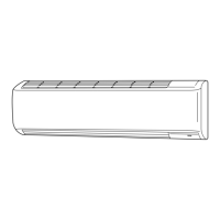
Fig. 3-3
Type
Table 3-1 Unit : inch (mm)
Length
1/2
1/2
Suspension lug
Drain connection
Refrigerant tubing joint (narrow tube side)
A
E
F
B
C
D
Refrigerant tubing joint (wide tube side)
1095_X_I
3. How to Install the Indoor Unit
■ Recessed Type (XS Type)
3-1. Suspending the Indoor Unit
This unit uses a drain pump. Use a carpenter’s level to
check that the unit is level.
3-2. Preparation for Suspending
(1) Fix the suspension bolts securely in the ceiling
using the method shown in the diagrams (Figs.
3-1 and 3-2), by attaching them to the ceiling
support structure, or by any other method that
ensures that the unit will be securely and safely
suspended.
(2) Follow Fig. 3-2 and Table 3-1 to make the holes
in the ceiling.
(3) Determine the pitch of the suspension bolts using
the supplied full-scale installation diagram. The
diagram and table (Fig. 3-3 and Table 3-2) show
the relationship between the positions of the
suspension fitting, the unit, and the panel.
A
(Ceiling opening)
B
(Suspention bolt pitch)
Refrigerant
tubing side
Drain hose
side
Unit : inch
Power line
(conduit size : 1/2)
Control line
32-9/32
(Ceiling opening)
23-7/32
(Suspention bolt pitch)
1094_X_I
Fig. 3-2
Type
Length
XS2432 (PNR-XS2432) 32-9/32 (820) 28-3/4 (730)
XS3632, XS4232
43-11/16 (1,110) 40-5/32 (1,020)
(PNR-XS3632)
AB
Table 3-2 Unit: inch (mm)
ABCDEF
XS2432 (PNR-XS2432)
5-29/32 (150) 7-7/8 (200) 10-1/32 (255) 11-23/32 (298) 4-29/32 (125) 6-1/2 (165)
XS3632, XS4232
6-1/2 (165) 9-1/4 (235) 11-7/32 (285) 12-29/32 (328) 4-29/32 (125) 6-1/2 (165)
(PNR-XS3632)