EasyManua.ls Logo

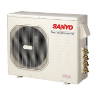
Sanyo CM2472A User Manual

Sanyo CM2472A
125 pages
To Next Page IconTo Next Page
Page #1 background imageLoading...
Page #1 background image
Notice
CORRECTION
SERVICE FLASH
PRODUCTION CHANGE
ADDED INFORMATION
REFERENCE NO. SM700856-03
FILE NO.
Page No.
of the Manual
Contents
Table 6
Reason
for change
Please add this notice to the TECHNICAL & SERVICE MANUAL listed below.
The reason for change
< Reference No. >
Current
A : Correction B : Quality reliability C : Standardization
D : Design change E : Addition of parts F : New information
Category :
Model :
Destination :
Serial No. :
North America
Issue Number : 3
DC INVERTER MULTI-SYSTEM AIR CONDITIONER
CM1972A
CM2472A
CM3172A
Date : June, 2011
New
SM700856-03SM700856-02
A
Product Code No.
1 852 356 14
1 852 356 11
1 852 356 12
Capacity at 230V
19,700 BTU/h
25,400 BTU/h
30,600 BTU/h
Outdoor Model No.
CM1972A
CM2472A
CM3172A
Fuse or Circuit Capacity of CM1972A : 20 15
APPENDIX A
21

Questions and Answers:

Sanyo CM2472A Specifications

General IconGeneral
TypeSplit System
Power Consumption (Cooling)2.2 kW
Power SupplySingle Phase, 50Hz
Noise Level (Indoor)45 dB(A)
Noise Level (Outdoor)55 dB(A)
Cooling Capacity24000 BTU/h

Summary

Notice

Update Information

Details about the notice including reason for change and reference numbers.

Product Information

Specifies the product category and model numbers.

Technical Specifications Summary

Summary of capacity, outdoor model, and product codes.

TECHNICAL & SERVICE MANUAL

Product Identification

Identifies the outdoor unit models and destination.

Applicable Indoor Units Overview

Overview of applicable wall-mounted and semi-concealed indoor unit types.

Important Refrigerant Information

Highlights the use of R410A refrigerant and servicing attention.

SAFETY PRECAUTIONS

General Electrical Safety

Precautions for electrical work, wiring, power supply, and component handling.

Component Handling Safety

Safety measures for handling capacitors and working with wet hands.

Wiring and Connection Safety

Ensuring secure wiring and proper attachment of covers for safety.

Symbol Explanations

Explanation of warning, prohibition, and attention symbols.

SAFETY PRECAUTIONS

Refrigerant Handling and Installation Safety

Safety measures for refrigerant, working at heights, and unit relocation.

Battery and General Cautions

Battery handling, water washing, humidity, and component check precautions.

Maintenance and Cleaning Safety

Safety during cleaning, part handling, and checking drainage.

REFRIGERANT R410A: SPECIAL PRECAUTIONS

R410A Characteristics

Details on R410A composition, properties, and characteristics.

Pre-Servicing Checklist

Essential checks and precautions before performing servicing.

Specialized Tools and Procedures

Tools and procedures for R410A tubing installation and servicing.

Compressor and Refrigerant Troubleshooting

Procedures for compressor malfunction and refrigerant leak handling.

Refrigerant Charging and System Retrofitting

Instructions for charging refrigerant and retrofitting existing systems.

APPLICABLE INDOOR UNITS

Indoor Unit Types and Combinations

Compatibility of wall-mounted and semi-concealed indoor units.

1. OPERATING RANGE

Temperature Limits

Indoor and outdoor air intake temperature ranges for operation.

2. SPECIFICATIONS

2-1. Unit Specifications

Technical data for the outdoor unit, including capacity, power, and dimensions.

2. SPECIFICATIONS

2-2. Major Component Specifications

Specifications for key components like PCB, compressor, and fan motor.

2. SPECIFICATIONS

2-3. Other Component Specifications

Specifications for sensors, including resistance vs. temperature charts.

3. DIMENSIONAL DATA

Outdoor Unit Dimensions

Diagrams showing the dimensions and service valve locations for CM1972A.

4. REFRIGERANT FLOW DIAGRAM

Refrigerant Flow Schematic

Schematic of the refrigerant flow path through the outdoor unit.

Refrigerant Tubing Insulation

Guidelines for insulating refrigerant tubing to prevent heat loss and condensation.

5. PERFORMANCE DATA

5-1. Temperature Charts (CM1972A)

Performance charts showing cooling characteristics for CM1972A outdoor unit.

5. PERFORMANCE DATA

5-1. Temperature Charts (CM2472A)

Performance charts showing cooling characteristics for CM2472A outdoor unit.

5. PERFORMANCE DATA

5-1. Temperature Charts (CM3172A)

Performance charts showing cooling characteristics for CM3172A outdoor unit.

5. PERFORMANCE DATA

5-2. Cooling Capacity Tables

Tables showing cooling capacity at various indoor/outdoor temperature conditions.

6. ELECTRICAL DATA

6-1. Electric Wiring Diagrams

Wiring diagrams for the outdoor unit CM1972A.

6. ELECTRICAL DATA

6-1. Electric Wiring Diagrams

Wiring diagrams for the outdoor unit CM2472A.

6. ELECTRICAL DATA

6-1. Electric Wiring Diagrams

Wiring diagrams for the outdoor unit CM3172A.

7. FUNCTIONS

7-1. Explanation of Functions

Explanation of unit operation modes like INITIAL, COOL, and SENSOR DRY.

7. FUNCTIONS

7-1. Explanation of Functions

Explanation of COOL mode, freeze prevention, stop, and restart conditions.

Frequency Control Table

Table showing frequency control based on outdoor air temperature.

7. FUNCTIONS

7-1. Explanation of Functions

Explanation of SENSOR DRY mode, including DRY A and DRY B operations.

1/f Fluctuation Fan Operation

Description and illustration of the 1/f fluctuation fan operation.

Low Ambient Cooling Operation

Conditions and Mode Changes

Conditions for switching to low ambient cooling operation.

Operation in Low Ambient Conditions

Fan speed adjustment and protective actions in low ambient conditions.

7-2. Protective Functions

7-2-1. Current Control

Automatic reduction or stoppage of operation to control operating current.

Automatic Frequency Control

Details of automatic frequency control for current reduction and prohibition.

7-2. Protective Functions

Current Control Details

Graphical explanation of current control limits for frequency reduction.

Low Start Current and Compressor Temperature Control

Protective functions for stable start current and compressor temperature.

8. TROUBLESHOOTING

8-1. Pre-Inspection Safety Precautions

Safety precautions for inspecting and repairing electronic circuits, especially capacitors.

8. TROUBLESHOOTING

8-2. Trouble Diagnosis by Error Lamps

Using error monitor lamps on the outdoor unit to diagnose faults.

Error Lamp Location and Display

Location of error lamps and interpretation of error codes.

8. TROUBLESHOOTING

8-3. Checking the Outdoor System

Procedure to check outdoor unit operation by applying voltage and shorting terminals.

8. TROUBLESHOOTING

8-4. Trouble Diagnosis of Each Part

Table mapping problems to inspection points for indoor and outdoor unit parts.

Part-Specific Inspection Points

Cross-reference of common problems with specific inspection points.

8. TROUBLESHOOTING

8-4-2. Inspection Points for Each Part

Specific inspection procedures for components like fuses, compressors, and sensors.

8. TROUBLESHOOTING

Component Troubleshooting

Troubleshooting steps for electric expansion valve, breaker, and refrigerant gas pressure.

Sensor Checks

Checking the branch tubing temperature sensor installation.

8. TROUBLESHOOTING

Refrigerant Gas Pressure Diagnosis

Diagnosing refrigerant shortage vs. circuit blockage and checking for leaks.

8. TROUBLESHOOTING

8-5. Fan Motor Trouble Diagnosis

Procedure for diagnosing issues with the outdoor DC fan motor.

REFRIGERANT R410A: SPECIAL PRECAUTIONS

R410A Characteristics

Details on R410A composition, properties, and characteristics.

Servicing Precautions

General precautions for servicing R410A units, including oil type.

REFRIGERANT R410A: SPECIAL PRECAUTIONS

9-2. Servicing Checklist

Essential checks and precautions before performing servicing.

Tubing and Flare Specifications

Specifications for R410A tubing and flare tool usage.

R410A Usage Restrictions

Restrictions on compressor oil and refrigerant types for R410A systems.

Fire and Leak Cautions

Safety measures if R410A is exposed to fire or leaks.

REFRIGERANT R410A: SPECIAL PRECAUTIONS

9-3. Tools Specifically for R410A

List of specialized tools required for servicing R410A systems.

Commonly Used Tools and Tubing Procedures

Commonly used tools and guidelines for refrigerant tubing installation.

9-5. Compressor Malfunction

Compressor Replacement Procedure

Step-by-step procedure for replacing the compressor.

Evacuation Time Standards

Table showing standard evacuation times based on tubing length.

9-5. Compressor Malfunction

Recharging Refrigerant

Instructions for recharging refrigerant after service, including cylinder handling.

9-6. Refrigerant Leaks

Leak Detection and Repair

Steps for detecting, recovering, sealing, and evacuating refrigerant leaks.

Evacuation Time Standards

Table showing standard evacuation times based on tubing length.

9-6. Refrigerant Leaks

Refrigerant Recharging

Recharging refrigerant after leak repair and evacuation.

9-7. Charging Additional Refrigerant

Extended Tube Refrigerant Charge

Instructions for charging refrigerant when tubes are extended.

9-8. Retro-Fitting Existing Systems

Compatibility with Existing Components

Guidelines on using existing units and tubing with R410A systems.

APPENDIX A INSTALLATION INSTRUCTIONS

Model Coverage

Manual covers installation for CM1972A, CM2472A, and CM3172A outdoor units.

INSTALLATION INSTRUCTIONS

Outdoor Unit Model Coverage

Installation guide for CM1972A, CM2472A, and CM3172A outdoor units.

IMPORTANT!

Pre-Installation Guidelines

Essential safety and operational guidelines before installation.

IMPORTANT!

Pre-Installation Guidelines

Essential safety and operational guidelines before installation.

Special Precautions

Safety measures for wiring, transporting, and installing units.

Servicing and General Safety

Safety steps before servicing and general safety measures.

1. GENERAL

Installation Tools and Materials

Lists of required tools, accessories, optional kits, and materials for installation.

2. INSTALLATION SITE SELECTION

Indoor Unit Site Selection

Guidelines and AVOID conditions for selecting the indoor unit installation site.

Outdoor Unit Site Selection

Recommended practices for outdoor unit placement, clearances, and base.

Installation Cautions

Cautions regarding airflow blockage, ceiling height, and floor clearance.

2. INSTALLATION SITE SELECTION

Table 3: Tubing Length and Refrigerant Requirements

Table detailing tubing length, elevation difference, and refrigerant requirements.

2. INSTALLATION SITE SELECTION

2-2. Connecting Indoor Units (CM1972A)

Diagrams showing types of indoor unit connections for CM1972A.

2. INSTALLATION SITE SELECTION

2-2. Connecting Indoor Units (CM2472A)

Diagrams showing types of indoor unit connections for CM2472A.

2. INSTALLATION SITE SELECTION

2-2. Connecting Indoor Units (CM3172A)

Diagrams showing types of indoor unit connections for CM3172A.

2. INSTALLATION SITE SELECTION

2-3. Outdoor Unit Placement

Guidelines and AVOID conditions for selecting the outdoor unit installation site.

2-4. Baffle Plate Installation

Recommendation and procedure for installing baffle plates for wind protection.

2. INSTALLATION SITE SELECTION

Baffle Plate Dimensions and Parts

Dimensions and required parts for baffle plate installation.

2. INSTALLATION SITE SELECTION

Baffle Plate Installation Procedure

Step-by-step instructions for installing air intake and discharge baffles.

Installation Precautions for Baffles

Precautions during baffle plate installation, including surface protection and drilling.

2. INSTALLATION SITE SELECTION

2-5. Outdoor Unit Outer Dimensions

Dimensional diagrams for CM1972A, CM2472A, and CM3172A outdoor units.

2. INSTALLATION SITE SELECTION

2-6. Outdoor Unit Installation Diagram

Diagram showing installation clearances and connections for indoor/outdoor units.

3. INSTALLATION PROCESS

Tubing and Wiring Embedding

Instructions for embedding and bundling tubing and wiring.

Flaring Method and Procedure

Explanation and steps for flaring copper tubes for connections.

3. INSTALLATION PROCESS

Flaring Procedure Details

Procedure for making a good flare on copper tubes.

Tubing Connection Cautions and Torque

Precautions and torque specifications for connecting refrigerant tubes.

3. INSTALLATION PROCESS

Refrigerant Tubing Insulation

Instructions for insulating refrigerant tubing for wall-mounted and ceiling units.

Insulation Material Requirements

Requirements for insulation material used in the system.

Tubing and Wiring Matching Caution

Caution to ensure correct matching of tubing and wiring connections.

3. INSTALLATION PROCESS

Taping the Tubes

Procedure for taping refrigerant tubes and drain hose together.

Finishing the Installation

Final steps for sealing holes and finishing the installation.

4. Air Purging

Effects of Air and Moisture

Explains the negative effects of air and moisture in the refrigerant system.

Air Purging with Vacuum Pump

Procedure for air purging using a vacuum pump.

R410A Charging Port Caution

Caution regarding R410A charging ports and required tools.

4. Air Purging

Purging Tool Cautions

Cautions regarding the use of manifold valves and vacuum pump adapters.

Evacuation Time Standards

Table showing required time for evacuation with a vacuum pump.

4. Air Purging

Pump Down Procedure

Procedure for recovering refrigerant gas using pump down.

Pump Down Definition and Limitations

Definition, purpose, and conditions for the pump-down procedure.

5. Wiring Instructions

General Wiring Precautions

General safety and connection precautions for wiring.

Wire Length and Diameter Recommendations

Guidelines for wire length, diameter, and fuse capacity based on model.

5. Wiring Instructions

5-3. Wiring System Diagrams

Wiring system diagrams for 3-indoor unit and 4-indoor unit configurations.

Wiring Safety Warnings

Warnings for complying with local codes, wire connection, and avoiding contact with parts.

Wiring Connection Cautions

Cautions regarding power supply connection, wiring placement, and grounding.

5. Wiring Instructions

5-4. Connecting Wires to Terminals

Instructions for connecting wires to indoor and outdoor unit terminals.

Wiring Connection Safety Warning

Warning about the risks of loose wiring, including overheating and fire.

5. Wiring Instructions

5-5. Outdoor Unit Wiring Instructions

Instructions for connecting inter-unit cables A, B, C, D to the outdoor unit.

Grounding and Cable Labeling

Importance of grounding and using labels for correct inter-unit cable connections.

6. Test Run

Test Run Procedure

Instructions for performing the test run for connected indoor units.

Tubing and Wiring Checks

Checking for errors in tubing and wiring after the test run.

Test Run Safety Caution

Caution to stop operation immediately if errors are found in tubing or wiring.

7. Connecting a Home Automation device

HA Terminal Connection

Location and connection of the HA 4P terminal on the indoor unit PCB.

8. Installation Check Sheet

Final Installation Verification Checklist

Checklist for verifying proper installation of units, wiring, refrigerant circuit, and connections.

APPENDIX B UNIT COMBINATION TABLES

List of Combination Tables

List of unit combination tables for different outdoor units.

Combination Table References

Combination tables for CM1972A, CM2472A, and CM3172A outdoor units.

Multi-Unit Operation Note

Note on operating multi-unit systems with 2 or more indoor units.

3-Room Outdoor Unit Combination Table

CM1972, A Combinations

Combinations of connectable indoor units for CM1972A outdoor unit.

Connection Conditions

Conditions for connecting indoor units to the multi outdoor unit.

Operation Capacity Example

Example calculation for total cooling capacity of connected indoor units.

Concurrent Operation Caution

Caution regarding concurrent operation of all indoor units.

Voltage Specific Notes

Notes specific to 230V and 208V operation.

< Combinations of operatable indoor units >

CM1972, A (230V) Unit Combinations

Table listing wall-mounted indoor unit combinations for CM1972A (230V).

< Combinations of operatable indoor units >

CM1972, A (208V) Unit Combinations

Table listing ceiling-mounted indoor unit combinations for CM1972A (208V).

4-Room Outdoor Unit Combination Table

CM2472, A Combinations

Combinations of connectable indoor units for CM2472A outdoor unit.

Connection Conditions

Conditions for connecting indoor units to the multi outdoor unit.

Operation Capacity Example

Example calculation for total cooling capacity of connected indoor units.

Concurrent Operation Caution

Caution regarding concurrent operation of all indoor units.

Voltage Specific Notes

Notes specific to 230V and 208V operation.

< Combinations of operatable indoor units >

CM2472, A (230V) Unit Combinations

Table listing wall-mounted indoor unit combinations for CM2472A (230V).

Concurrent Operation Prohibition

Important note prohibiting concurrent operation of four indoor units.

< Combinations of operatable indoor units >

CM2472, A (208V) Unit Combinations

Table listing ceiling-mounted indoor unit combinations for CM2472A (208V).

4-Room Outdoor Unit Combination Table

CM3172, A Combinations

Combinations of connectable indoor units for CM3172A outdoor unit.

Connection Conditions

Conditions for connecting indoor units to the multi outdoor unit.

Operation Capacity Example

Example calculation for total cooling capacity of connected indoor units.

Concurrent Operation Caution

Caution regarding concurrent operation of all indoor units.

Voltage Specific Notes

Notes specific to 230V and 208V operation.

< Combinations of operatable indoor units >

CM3172, A (230V) Unit Combinations

Table listing wall-mounted indoor unit combinations for CM3172A (230V).

< Combinations of operatable indoor units >

CM3172, A (230V) Unit Combinations

Table listing ceiling-mounted indoor unit combinations for CM3172A (230V).

4-Room Outdoor Unit Combination Table

CM3172, A Combinations

Combinations of connectable indoor units for CM3172A outdoor unit.

Connection Conditions

Conditions for connecting indoor units to the multi outdoor unit.

Operation Capacity Example

Example calculation for total cooling capacity of connected indoor units.

Concurrent Operation Caution

Caution regarding concurrent operation of all indoor units.

Voltage Specific Notes

Notes specific to 230V and 208V operation.

< Combinations of operatable indoor units >

CM3172, A (230V) Unit Combinations

Table listing wall-mounted indoor unit combinations for CM3172A (230V).

< Combinations of operatable indoor units >

CM3172, A (208V) Unit Combinations

Table listing ceiling-mounted indoor unit combinations for CM3172A (208V).

Related product manuals