L
‘L
L
Service Manual
Contents
IFILE NO.
I
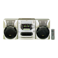
Mini Component System
DC-C30 (AU)
Specifications ................................................................... 1
What to do if ..................................................................... 1
Laser beam safety precaution ..........................................2
CD pick-up maintenance ..................................................2
Service mode ...................................................................2
CD player adjustments .....................................................3
Tape adjustments ............................................................4
Tuner adjustments ...........................................................6
Exploded view
(Cabinet & Chassis) .....................................................7
(Tape mechanism)
........................................................ 15
(CD changer mechanism) ............................................. 16
(CD base mechanism)
..................................................l7
Parts list
(Cabinet & Chassis) ...................................................... 8
(Tape mechanism)
........................................................ 14
(CD mechanism)
........................................................... 17
PRODUCT CODE No.
12955605
IC
block diagram & description ........................................ 18
FL display description ......................................................23
IC & Transistor voltages ...................................................24
Wiring connection ............................................................25
Schematic diagram
(TUNER) .......................................................................26
(AMPLIFIER) .................................................................28
(FRONT) .......................................................................32
(CD)
...............................................................................
36
(DEcK) ..........................................................................4o
Wiring diagram
(TUNER & AMPLIFIER) ................................................ 30
(FRONT) ....................................................................... 34
(CD)
...............................................................................
38
(DECK) .......................................................................... 39
(POWER TRANSFORMER) ........................................42
(POWER SWITCH, DISC SWITCH) ...........................43
——— ——— —.— ——— ——— ——— ———
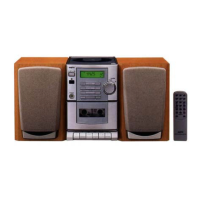
‘This service manual consists of “DC-C30U” (Main unit: 129555 05), T
I
I
~RB-C30’ (Remote control) and “SX-C30’ (Speaker system: 133 68402)ti
——— ——— ——— ——— —.— .—— ———
REFERENCE No. SM581OO47