EasyManua.ls Logo

Sanyo DC-DA70 - User Manual

Sanyo DC-DA70
32 pages
To Next Page IconTo Next Page
Loading...
FILE NO.
Service Manual
Micro Component System
DC-DA70 (AU)
(PA)
PRODUCT CODE No.
129 573 04 (AU)
129 573 05 (PA)
REFERENCE No. SM5810135
SPECIFICATIONS
General
Output power ......................... 4 W x 2 (at 4 ohms, 10% distortion)
Outputs .................................. SPEAKERS : 4 ohms
PHONES : 8 - 32 ohms
Power requirements............... AC 230 - 240 V, 50 Hz (AU)
AC 110-120V/220-240V,
50/60Hz (PA)
Power consumption ............... 19 W
Dimensions (W x H x D) ........ Approx. 140 x 210 x 200 mm
Weight.................................... Approx. 2.2 kg
Speaker system
Type ....................................... Full range bass reflex
Drivers ................................... 10 cm cone type
Maximum
power-handling capacity ..... 6 W (peak)
Nominal impedance ............... 4 ohms
Dimensions (W x H x D) ........ Approx. 140 x 210 x 184 mm
Weight.................................... Approx. 1.2 kg (per speaker)
Specifications subject to change without notice.
Tuner
Reception frequency .............. FM : 87.5 - 108.0 MHz
AM : 522 - 1710 kHz(9KHz step)
520 - 1710 kHz(10KHz step)
CD player
Channels................................ 2-channel stereo
Sampling frequency ............... 44.1 kHz
Pick-up ................................... Optical 3-beam
semiconductor laser
Wave length ........................... 790 nm
Wow and Flutter..................... Below measurable limits
Cassette deck section
Track system ......................... 4-track, 2-channel stereo
Frequency response .............. 80 Hz - 15kHz
Signal to noise ratio ............... 40 dB
Wow and Flutter..................... 0.15% (WRMS)
Fast forward / Rewind time .... Approx. 110 sec. (C-60)
PA : This service manual consists of "DC-DA70U" (Main unit : 129 572 05)
and "SX-DA70" (Speaker system : 165 006 00).
AU : This service manual consists of "DC-DA70U" (Main unit : 129 572 04)
and "SX-DA70" (Speaker system : 165 006 00).
Question and Answer IconNeed help?

Do you have a question about the Sanyo DC-DA70 and is the answer not in the manual?

Sanyo DC-DA70 Specifications

General IconGeneral
CD PlayerYes
TunerFM/AM
TypeMicro Music System
FunctionsCD, Radio, Amplifier
Frequency response20Hz - 20kHz

Summary

System Specifications and Safety

Product Specifications

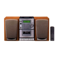
Details of tuner, CD player, cassette deck, general, and speaker system.

Laser Beam Safety Precautions

Safety warning regarding laser beam exposure when operating the CD player.

Maintenance and Adjustments

Procedures for cleaning the CD pick-up lens and adjusting CD player settings.

Component and Adjustment Procedures

Tape Adjustment Procedures

Steps for replacing heads, adjusting azimuth, motor speed, and mechanism torques.

Tuner Adjustment Procedures

Alignment procedures for FM and AM tuner sections using specific test signals.

Exploded View - Cabinet & Chassis

A visual breakdown of the main unit's cabinet and chassis components.

Parts List

Product Safety Notice

Important safety instructions for servicing and component replacement.

Packing & Accessories

List of included packing materials and accessories for the product.

Cabinet & Chassis Parts

Identification and part numbers for cabinet and chassis components.

Electrical Components

List of electrical parts including resistors, capacitors, transistors, and ICs.

Board Assemblies

Part numbers and descriptions for various printed circuit board assemblies.

Mechanisms

Parts list for the tape and CD mechanisms.

Integrated Circuit Details

Tuner and Micro Processor ICs

Block diagrams and descriptions for Tuner (LA1186N, LA1844ML) and Micro Processor (LC72336-9921) ICs.

CD, Amplifier, and Driver ICs

Block diagrams for CD, Amplifier, and Motor Driver ICs (LA9241M, LC78622NE, BA3314, TA8229K, LC75392, LA6541).

Digital Signal Processor IC

Block diagram and description for the Digital Signal Processor IC (LC78622E).

Schematic Diagrams

Tuner Schematics

Circuit diagrams for the Tuner section (AU and PA versions).

Amplifier Schematics

Circuit diagrams for the Amplifier section (AU and PA versions).

Front and CD Schematics

Circuit diagrams for the Front and CD sections.

Wiring Diagrams

CD & Front Wiring

Wiring connections for the CD and Front sections.

LED & Power Wiring

Wiring diagrams for the LED and Power Transformer boards.

Tuner Wiring (AU;PA)

Wiring diagrams for the Tuner section in AU and PA versions.

Amplifier Wiring (AU;PA)

Wiring diagrams for the Amplifier section in AU and PA versions.

System Block Diagrams

Overall System Block Diagram

A summary block diagram showing the interaction between Tuner, CD, and Amp sections.

Wiring Connection Diagram

Inter-Board Wiring

Diagram showing how the main PCBs and mechanisms are interconnected.

FL Display Description

Front Panel Display Layout

Description of the FL display segments and their corresponding modes/functions.

Voltage Table

IC and Transistor Voltage Readings

Table listing expected voltage measurements for various ICs and transistors.

Related product manuals