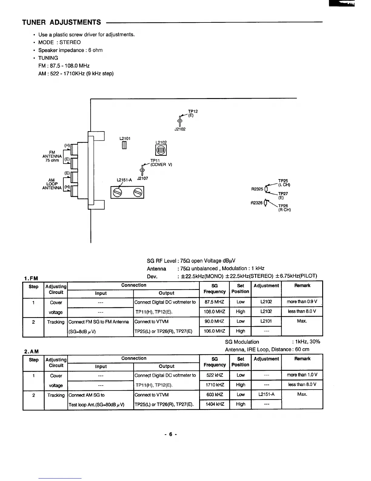
TUNER ADJUSTMENTS
● Use a plastic screw driver for adjustments.
● MODE :STEREO
● Speaker impedance: 60hm
● TUNING
FM :87.5 -108.0 MHz
AM: 522-171 OKHZ (9 kHz step)
(H)
FM
c
‘~j:}:A (E)
(E)
AM
c
AfiTyNkA (H)
TP12
ff
(E)
J2102
L2101
Iml
L2102
❑
R
TP1l
f’
(COVER V)
K!151-A ‘2’07
h
TP25
c
(L CH)
R2325
TP27
w
(E)
R2326
TP26
(R CH)
SG RF Level : 75Q open Voltage dBpV
Antenna : 75f2 unbalanced, Modulation :1 kHz
d Cmi
Dev. : *22.5kHz(MONO) *22.5kHz(STEREO) *6.75kHz(PlLOT)
o.rm
Step
Adjusting
Connection
SG
set
Adjustment Remark
Circuit
Input
output
Frequency Position
1 Cover
---
Connect Digital DCvoltmeter to 87.5 MHZ Low
L21CK2
mcfe than 0.9 V
voltage
---
TP1 l(H), TP12(E). 108.0 MHZ
High
L21CQ
less than 8.0 V
2 Tracking
Connect FM SG to FM Antenna Connect to VTVM
90.0 MHZ
Low
El
01 Max.
(SG=8dB P V)
TP25(L) or TP26(R), TP27(E) 106.0 MHZ
High
___
----
2.AM
Step
1
2
Adjusting
Conr
Circuit
Input
Cover I
---
voltage
I
---
Tracking
Connect AM SG to
Test loop Ant.(SG=60dB JJW
?ction
output
Conned Digital DC voltmeter to
TP1 l(H), TP12(E).
Connect to VTVM
TP25(L) or TP26(R), TP27(E).
SG Modulation
:1 kHz, 30?X0
Antenna, II
*
=-t=
1404 kHZ I High
IE Loop, Distance:
60 cm
Adjustment
Remark
I
,
---
I
more than 1.0 V
1
---
I less than 8.0 V I
-6-