,..
i
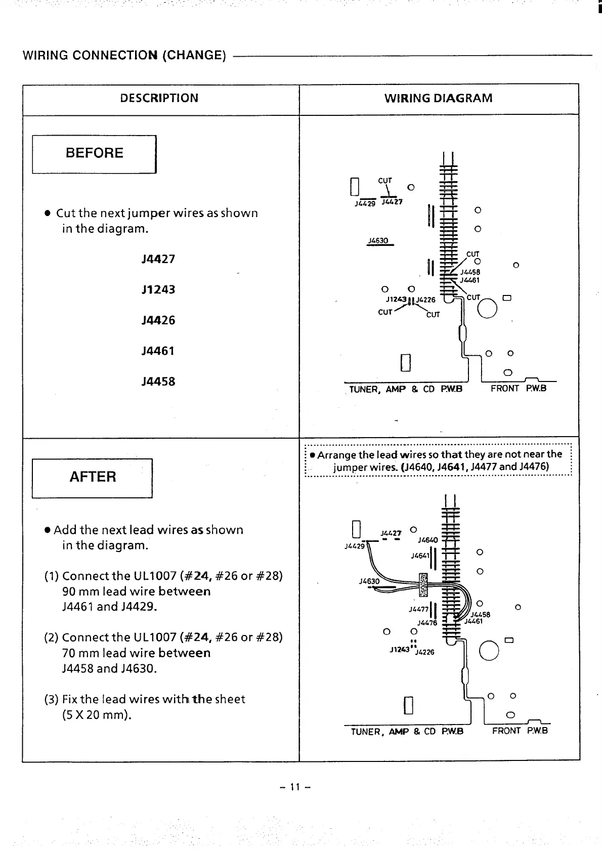
WIRING CONNECTIOI!4 (CHANGE)
DESCRIPTION
WIEUNG DIAGRAM
E
u
pvro g
J&~ Jti27
●
Cut the next jumper wires as shown
II==
?%O
in the diagram.
-o
J4427
II
~ cu&
‘~
(
~
J.@458
J&i61
J3243
o
5 ~w
J12= JL226
:T)<
o.
0
M426
CUT
J4461
II
00
J4458
o
n
TUNER, AMP & CD I?WB
FRONT P.W.B
.......................................................................................
~
● Arrange the lead wires so that they are not near the ~
m ‘“”””’”-”-”---””--;-””””””””””””
jumper wires. (J4640, J4641, J4477 and J4476) ;
%
● Add the next lead wires as shown
o
J442T 0
~
in the diagram.
.-
JM40
J4L2:
R
%
II
J,G,, q=F o
~
o
(1) Connect the UL1OO7
(#24, #26 or #28)
.= f,,=-
J.4630
90 mm lead wire between
J4461 and J4429-
~
II
14477 -
0
0
J4.458
-!4676
J4461
(2) Connect the UL1OO7 (#24, #26 or #28)
00s
#*
70 mm lead wire
between
Jl#;@G
J4458 and J4630.
(3) Fix
the lead wires with the sheet
II
(5 X20mm).
TUNER, AMP & CD P.W.!3
FRONT P.W.B
-11-
0

 Loading...