Do you have a question about the Sanyo DC and is the answer not in the manual?
Technical specifications for the cassette deck and amplifier components.
Technical specifications for the tuner, timer, and CD player units.
Specifications for the remote controller unit.
Specifications for the speaker systems.
List of packing materials for the unit.
List of included accessories.
Parts list for the remote controller.
Parts list for the speaker unit.
FM band tuning adjustment steps.
AM band tuning adjustment steps.
Safe handling of CD pickup and semiconductor components.
Preventing static discharge during repair.
Instructions for cleaning the optical lens.
Pre-removal steps for CD mechanism.
Disc tray removal and installation procedure.
Steps for CD mechanism disassembly.
Replacing and lubricating the CD pickup.
Replacing the loading/sled motor.
Checking the CD motor operation.
Lubricating and mounting the tray slide.
Installing the base slide and timing gear.
Attaching the gear tension spring to the timing gear.
Lubricating the base lever.
Lubricating the pickup sled and clutch gears.
Arranging and securing leads for reassembly.
Confirming the clock output in service mode.
Performing timer debugging.
Checking key input signals.
Checking LCD connections.
Checking system connector signals.
CD tracking balance adjustment mode.
CD operation display mode.
Displays shown during CD operation mode.
General electrical adjustments for CD player.
Tools and tests for CD adjustment.
Setting initial adjustment controls.
Tracking balance adjustment procedure.
Additional tracking balance adjustments.
Steps to confirm focus gain.
Steps to confirm tracking gain.
Safety precautions for servicing.
List of cabinet parts.
List of chassis parts.
List of screws and fixing parts.
List of electrical components.
Parts list for the tuner PC board assembly.
Parts list for the CD Micon PC board assembly.
Parts list for the CD Main PC board assembly.
Parts list for the front PC board assembly.
Parts list for the LED PC board assembly.
Block diagram and pin functions for IC101.
Block diagram for IC102.
Block diagram and pin functions for IC103.
Block diagram and pin functions for IC104.
Block diagram and pin functions for IC105.
Block diagram for IC106.
Block diagram for IC107.
Block diagram for IC108.
Block diagram for IC109.
Block diagram for IC201.
Block diagram for IC202.
Block diagram for IC203.
Block diagram and pin functions for IC251.
Voltage table for IC101 in different modes.
Voltage table for IC102 in different modes.
Voltage table for IC103 in different modes.
Voltage table for IC104 in different modes.
Voltage table for IC105 in different modes.
Voltage table for IC106 in different modes.
Voltage table for transistors in different modes.
Adjustment procedure for the amplifier section.
Procedure for adjusting tape speed.
Location of tape deck adjustment parts.
Measurement of take-up, back, and tape tension.
Method for connecting and replacing the rotary head.
Instructions for replacing motors and belts.
Safety precautions for servicing.
List of cabinet parts.
List of electrical components.
List of screws and fixing parts.
List of chassis parts.
Parts list for the pre-amplifier PC board.
Parts list for the primary PC board.
Parts list for the secondary PC board.
Parts list for the speaker terminal PC board.
Parts list for the front PC board assembly.
Parts list for the front switch 1 PC board.
Parts list for the LED PC board assembly.
Parts list for the tape deck amplifier PC board.
Parts list for the regulator IC PC board.
Parts list for the front switch 2 PC board.
Diagram showing tape deck mechanism parts.
Parts list for the tape deck mechanism PC board.
Fixing parts for the tape deck mechanism.
Block diagram and pin functions for IC351.
Block diagram and pin functions for IC370.
Block diagram and pin functions for IC374.
Block diagram and pin functions for IC371.
Block diagram and pin functions for IC375.
Block diagram and pin functions for IC500.
Block diagram for IC501.
Block diagram and pin functions for IC551.
Block diagram for IC700.
Block diagram for IC702-802.
Block diagram for LA6458S ICs.
Block diagram for IC708.
Block diagram for IC705.
Block diagram for IC900-903.
Block diagram for IC901.
Block diagram for ICS02.
| Brand | Sanyo |
|---|---|
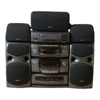
| Model | DC |
| Category | Stereo System |
| Language | English |