CD PLAYER ADJUSTMENT
, .,: .”......,’
. .. .. . . . . .
,,.
.,
:,.::;.,.’..
,,. ,
. . . ... .,
PROCEDURES (Continued)
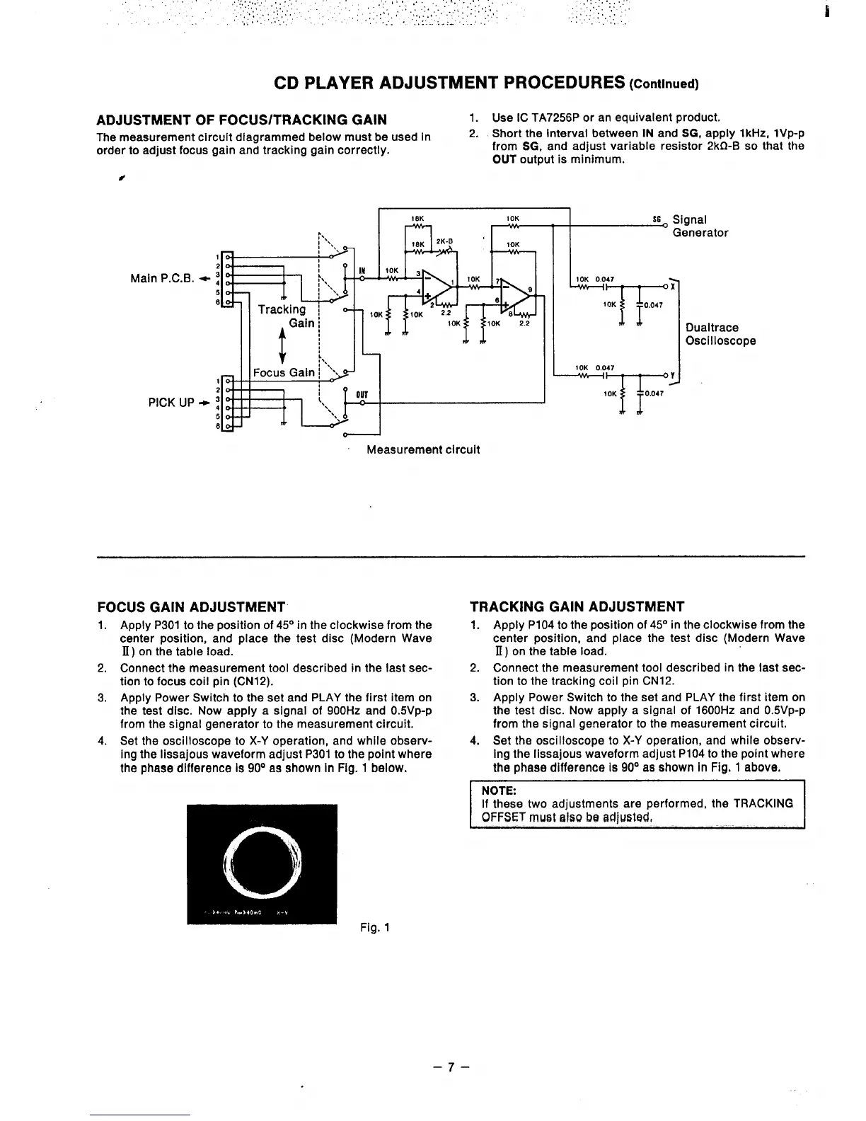
ADJUSTMENT OF FOCUS/TRACKING GAIN
1.
Use IC TA7256P or an equivalent product.
The measurement circuit diagramed below must be used in
2. Short the interval between IN and SG, apply 1
kHz, lVP-P
order to adjust
focus gain and tracking gain correctly.
from SG, and adjust variabie resistor 2kf2-B so that the
OUT output is minimum.
#
18K
10K
S6 signal
— —
Main P.C.B. ~
PICK UP +
Measurement circuit
II
Generator
h
L
10K 0.047
T’
x
10K
1
0,047
10K 0,047
T
Y
10K
I
0.047
Dualtrace
Oscilloscope
FOCUS GAIN ADJUSTMENT”
1. Apply P301 to the position of 45° in the clockwise from the
center position, and place the test disc (Modern Wave
II) on the tabie load.
2. Connect the measurement tool described in the last sec-
tion to focus coil pin (CN12).
3. Apply Power Switch to the set and PLAY the first item on
the test disc. Now apply a signal of 900Hz and 0.5VP-P
from the signal generator to the measurement circuit.
4. Set the oscilloscope to X-Y operation, and while observ-
ing the Iissajous waveform adjust P301 to the point where
the phase difference Is 90° as shown In Fig. 1 below.
TRACKING GAIN ADJUSTMENT
1.
2.
3.
4.
Apply P104 to the position of 45° in the clockwise from the
center position, and place the test disc (Modern Wave
B) on the table load.
Connect the measurement tool described in the last sec-
tion to the tracking coil pin CN12.
Apply Power Switch to the set and PLAY the first item on
the test disc. Now appiy a signal of 1600Hz and 0.5VP-P
from the signal generator to the measurement circuit.
Set the oscilloscope to X-Y operation, and while observ-
ing the Iissajous waveform adjust P104 to the point where
the phaae difference Is 90° as shown in Fig. 1 above.
NOTE:
If these two adjustments are performed, the TRACKiNG
OFFSET must talw
be adjusted,
ii
Fig. 1
–7–