KICK GAIN ADJUSTMENT
1.
2.
3.
4.
ii
CD PLAYER ADJUSTMENT PROCEDURES (Continued)
Place the test disc (Modern Wave II) on the table load.
Set the oscilloscope to NORMAL TRIG., set the EXT.
TRIG. pin to external trigger, and input the trigger from
test point TP1O (THLD) pin to the oscilloscope.
Next connect test point TP14 (HF) pin to Channel 1 of the
oscilloscope, and connect test terminal (CN15) TE
pin to
Channel 2.
Apply Power Switch to the set and PLAY the first item on
the test disc, and the press the PAUSE button. Now ob-
serve the waveforms for HF and TE with triggers applied
from test point TPIO (THLD) pin. At this point, adjust P105
so that a kick pulse waveform of about 1 to 1.5 tracks as
shown in Fig. 2 below is obtained.
O- Tracking Error Out
- HF waveform
L
Adjustment must be performed
so
curve section in Fig, 2 appears.
Fig. 2
CONFIRMING JITTER
If no jitter counter is available, this check does not have to be
have to be performed.
1, PLAY the fourth item on the test disc (Modern Wave II).
2. Connect an oscilloscope to the test point TP14 (HF) pin,
and check that its level is in the range 1.8Vp-p - 3.3 Vp-p,
3. Connect a jitter counter to test terminal (CN5) EFM pin,
and check that the 3T jitter value is less than 20ns.
(Window width: 600ns - 850ns, Set Level: 2.5V)
4. Now PLAY the tenth item on the test disc and check that
the jitter value is less than 20ns again.
ADJUSTMENT OF TURNTABLE HEIGHT
This adjustment must be performed when the Spindle Motor
is replaced.
1, The turntable should be mounted so that its upper surface
Is 13,75 mmk0.lmm above the surface of the chassis,
-%+73.75..
Chassis
+
[
1
I
t-
Spindle
Motor
2.
3.
4.
5.
Place the test disc (Modern Wave II) on the turntable.
Connect a DC Voltmeter and an oscilloscope via the low-
pass filter shown below to test terminal (CN1l) F (focus
coil) pin.
22K
‘T’”’’k;:::
Measurement circuit
Apply Power Switch to the set and PLAY the first item on
the disc.
If the DC Voltmeter reading is not in the ranges OV&O.2V
for inner tracks and OV+-O.35V for outer tracks, then the
turntable height must be readjusted. Raise the turntable
higher if the DC Voltmeter indicator is on the plus (+)
side, and lower it if it is on the minus (–) side.
(With this circuit lV represents movement of approxi-
mately 0.55mm - 0.65mm.)
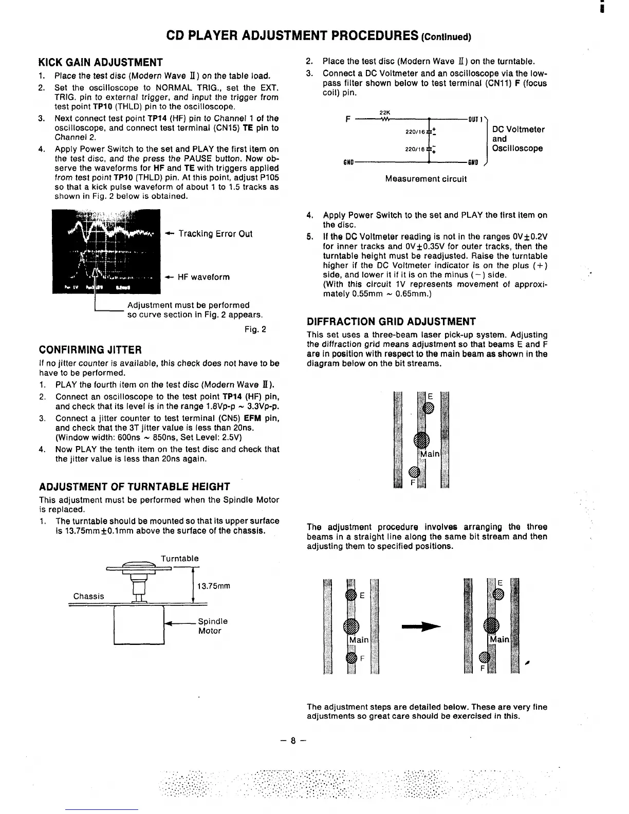
DIFFRACTION GRID ADJUSTMENT
This set uses a three-beam laser pick-up system. Adjusting
the diffraction grid means adjustment so that beams E and F
are in position with respect to the main beam as shown in the
diagram below on the bit streams.
The adjustment procedure involves arranging the three
beams in a straight line along the same bit stream and then
adjusting them to specified positions.
The adjustment steps are detailed below. These are very
adjustments so great care should be exercised in this.
–8–
line
.