CD CHANGER REPLACEMENT
.-.
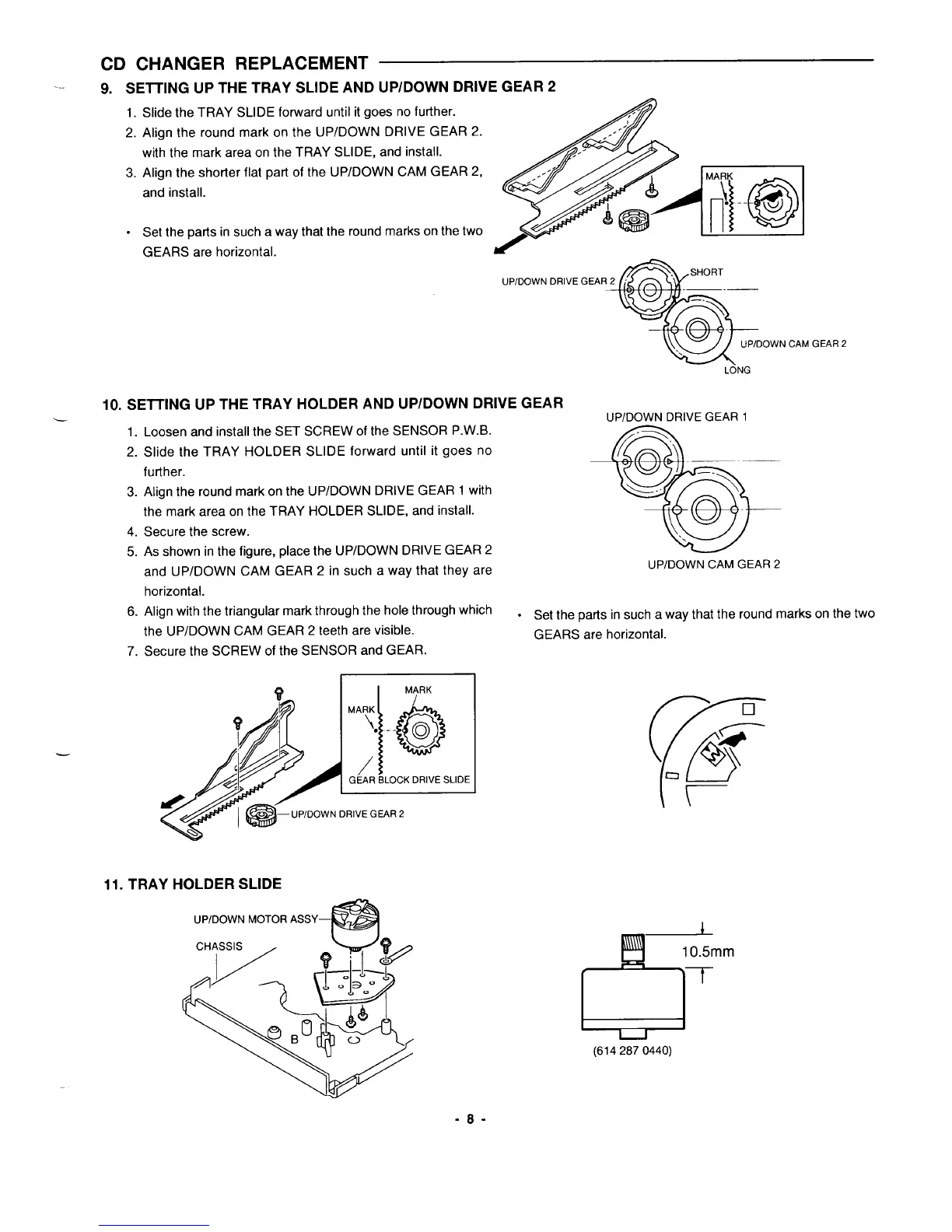
9. sETTING uPTHETRAY sLIDEAND uP/DowNDRlvEGEAR2
1.
Slide the TRAY SLIDE forward until itgoesnofur’fher.
2. Align the round mark on the UP/DOWN DRIVE GEAR 2.
with the mark area on the TRAY SLIDE, and install.
3. Align the shorter flat part of the UPIDOWN CAM GEAR 2,
and install.
. Set the parts in such a way that the round marks on the two
GEARS are horizontal.
I
JP/DOWN DRIVE GEAR 2
—
10. SEITING UP THE TRAY HOLDER AND UP/DOWN DRIVE GEAR
1.
2.
3.
4.
5.
6.
7.
Loosen and install the SET SCREW of the SENSOR P.W.B.
Slide the TRAY HOLDER SLIDE forward until it goes no
further.
Align the round mark on the UP/DOWN DRIVE GEAR 1 with
the mark area on the TRAY HOLDER SLIDE, and install.
Secure the screw.
As shown in the figure, place the UP/DOWN DRIVE GEAR 2
and UP/DOWN CAM GEAR 2 in such a way that they are
horizontal.
Align with the triangular mark through the hole through which
the UP/DOWN CAM GEAR 2 teeth are visible.
Secure the SCREW of the SENSOR and GEAR.
11. TRAY HOLDER SLIDE
UPIDOWN MOTOR ASSY—
m
OWNCAMGEAR2
LONG
UP/DOWN CAM GEAR 2
● Set the parts in such a way that the round marks on the two
GEARS are horizontal.
b’
10.5mm
7
(61 4287 0440)
-8-
 Loading...


