FILE NO.
Service Manual
Contents
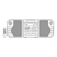
DC-S800 (XE)
PRODUCT CODE No.
129 575 02
REFERENCE No.
SM5810143
123
456
789
0
z/ON
TUNER
/BAND
SLEEP
ADJUST
SET/CLEAR
CLOCKTIMER
DISC SELECT
REPEAT
RANDOM MEMORY
n
PRESET
i
TIME SET
fe
TAPE-A/B REC MUTE
ncjd
a
REMOTE CONTROL REM-C30
SOUND
PRESET
VIDEO/DVD
MUTE
VOLUME
Specifications ...................................................................1
What to do if ..................................................................... 1
Laser beam safety precaution..........................................2
CD pick-up maintenance.................................................. 2
Service mode ...................................................................2
CD player adjustments..................................................... 3
Tape adjustments ............................................................4
Tuner adjustments ...........................................................6
Exploded view
(Cabinet & Chassis) ......................................................7
(Tape mechanism) ........................................................15
(CD changer mechanism) ............................................. 16
(CD base mechanism) .................................................. 17
Parts list
(Cabinet & Chassis) ......................................................8
(Tape mechanism) ........................................................15
(CD mechanism) ...........................................................17
IC block diagram & description ........................................ 18
IC & Transistor voltages ................................................... 23
FL display description ...................................................... 24
Schematic diagram
(TUNER) ....................................................................... 26
(AMPLIFIER) ................................................................. 28
(FRONT) ....................................................................... 34
(CD)............................................................................... 38
(DECK) .......................................................................... 42
Wiring diagram
(TUNER & AMPLIFIER) ................................................30
(POWER TRANSFORMER) ........................................ 32
(HEADPHONE, LED & REGULATOR) ......................... 33
(FRONT) ....................................................................... 36
(CD)............................................................................... 40
(DECK) .......................................................................... 41
(OPTICAL DIGITAL OUT & SUB TRANS )................... 44
Wiring connection ............................................................ 45
This service manual consists of "DC-S800U" (Main unit : 129 574 02), "RB-C30" (Remote control),
"SX-S800L" (Speaker system : 165 007 02) and "SX-S800R" (Speaker system : 165 008 02).
Micro Component System