— 13 —
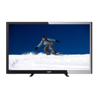
MAIN BOARD REMOVAL
Remove 5 screws (E: 3X10) to remove the main board
with the terminal base (TMNL/B) and audio output jacks
(MO/JACK) (assembly parts).
RC BOARD REMOVAL
Remove a screw (F: 4X14) to remove the RC board.
POWER BOARD REMOVAL
Remove 4 screws (G: 3X10) to remove the power board
with the chassis holder (CH/HLD) (assembly parts).
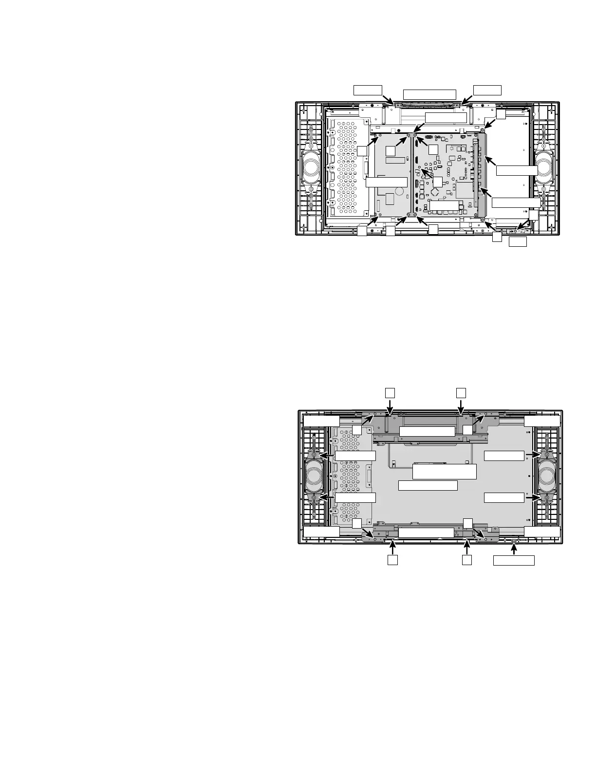
CONTROL BOARD REMOVAL
Press 2 hooks inside to remove the control board with
the panel top and button assembly.
SPEAKER REMOVAL
Remove 4 holders (SP/HLD) to remove speakers.
LCD PANEL REMOVAL
1. Remove 4 screws (H: 3X10) to remove the LCD
panel with the top (HLD/PNL-T) and bottom
(HLD/PNL-B) panel holders.
2. Remove 2 screws (J: 3X10) to remove the top
panel holder (HLD/PNL-T).
3. Remove 2 screws (I: 3X10) to remove the bottom
panel holder (HLD/PNL-B).
CABINET FRONT REMOVAL
1. Complete previous disassembly procedures.
2. Remove spacer (Buffer tape) and DEC-RC
(Decoration for remote control receiver).
Note: The spacers can be reused.
Chassis Base

 Loading...