1
S4359249
INSTALLATION INSTRUCTIONS
SANYO FISHER COMPANY
A DIVISION OF SANYO NORTH
AMERICA CORPORATION
21605 Plummer Street
Chatsworth, CA91311
IMPORTANT Page
Please Read Before Starting .................................. 2
1. GENERAL ............................................................. 3
1-1. Tools Required for Installation (not supplied)
1-2. Accessories Supplied with Unit
1-3. Optional Copper Tubing Kit
1-4. Type of Copper Tube and Insulation Material
1-5. Additional Materials Required for Installation
1-6. Operating Range
1-7. Tubing Length
2. SELECTING THE INSTALLATION SITE ............ 7
Indoor Unit
Outdoor Unit
2-1. Air Discharge Chamber for Top Discharge
2-2. Wind Shield for “CL” Model
3. HOW TO INSTALL THE INDOOR UNIT ............ 10
■ Recessed Type (XS Type) ................................ 10
3-1. Suspending the Indoor Unit
3-2. Preparation for Suspending
3-3. Placing the Unit Inside the Ceiling
3-4. Installing the Drain Piping
3-5. Checking the Drainage
3-6. Before Installing the Ceiling Panel
3-7. Installing the Ceiling Panel
3-8. When Removing the Ceiling Panel for
Servicing
3-9. Duct for Fresh Air
■ Ceiling-Mounted Type (TS Type)..................... 18
3-10. Suspending the Indoor Unit
3-11. Duct for Fresh Air
3-12. Installing the Drain Piping
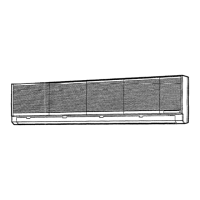
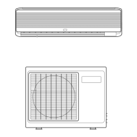
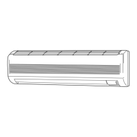
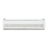
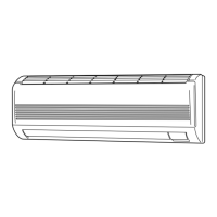
■ Wall-Mounted Type (KS Type) ........................ 22
3-13. Removing the Wall Fixture from the Unit
3-14. Selecting and Making a Hole
3-15. Installing the Wall Fixture onto Wooden or
Gypsum Wall
3-16.
Removing the Casing to Install the Indoor Unit
3-17. Removing the Grille to install the Indoor Unit
3-18. Preparing the Indoor Side Tubing
3-19. Wiring Instructions
3-20. Wiring Instructions for Inter-Unit Connections
3-21. Shaping the Tubing
3-22. Installing the Drain Hose
4. HOW TO INSTALL THE REMOTE
CONTROL UNIT ................................................. 33
■ Wireless Remote Control Unit
4-1. Mounting on a Wall (except KS2432A)
4-2. Mounting on a Wall (KS2432A only)
■
Wired Remote Control Unit (Option) (except 2432A)
4-3. Installing the Wired Remote Control Unit
CONTENTS
— Split System Air Conditioner —
85464359249001
5. ADDRESS SWITCHES (except KS2432A) ....... 36
5-1. Finding the Address Switches
5-2. Switch Positions for 2 Units or 2 Groups of
Units
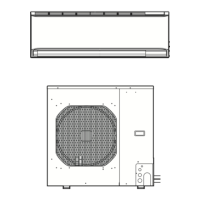
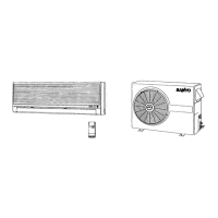
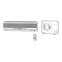
6. HOW TO INSTALL THE OUTDOOR UNIT ........ 37
6-1. Removing the Protective Spacer for
Transportation
6-2. Installing the Outdoor Unit
6-3. Tubing Direction
7. ELECTRICAL WIRING ....................................... 38
7-1. General Precautions on Wiring
7-2. Recommended Wire Length and Wire
Diameter for Power Supply System
7-3. Wiring System Diagram
7-4. Examples of Incorrect Wiring
7-5. How to Connect Wiring to the Terminal
8. HOW TO PROCESS TUBING ........................... 41
8-1. Use of the Flaring Method
8-2. Flaring Procedure with a Flare Tool
8-3. Precaution before Connecting Tubes Tightly
8-4. Precautions during Brazing
8-5. Connecting Tubing between Indoor and
Outdoor Units
8-6. Insulating the Refrigerant Tubing
8-7. Taping the Tubes
8-8. Finishing the Installation
9. AIR PURGING .................................................... 44
■ Air Purging with a Vacuum Pump
(for Test Run)
10.TEST RUN .......................................................... 47
10-1. Preparing for Test Run
10-2. Performing Test Run
10-3. Performing Test Run with Optional Wired
Remote Control Unit
■ Basic Functions of the Service Valves
■ Pump Down
Units should be installed by licensed contractor
according to local code requirements
Model Combinations
Combine indoor and outdoor units only as listed below.
Indoor units Outdoor units
XS2432 (PNR-XS2432) C2432A
TS2432 CL2432A
KS2432
KS2432A
KS3032 C3032A
CL3032A
XS3632 (PNR-XS3632) C3632A
TS3632 CL3632A
KS3632
XS4232 (PNR-XS3632) C4232A
TS4232 CL4232A
Power Supply: 60Hz, single-phase, 208/230 V