Do you have a question about the Sanyo KS3632 and is the answer not in the manual?
| Power Supply | 220-240V, 50Hz |
|---|---|
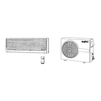
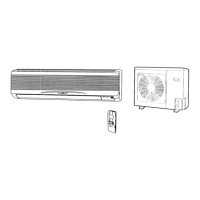
| Type | Split System |
| Cooling Capacity | 3600 W |
| Operating Temperature | 43°C |
| Weight | Indoor: 9 kg |
Crucial safety guidelines for electrical wiring to prevent shock or damage.
Guidelines for safely handling and moving the unit to prevent damage.
Important safety measures to follow during the installation process.
Safety instructions to be followed when performing maintenance or repairs.
Other essential safety advice and precautions for safe operation.
List of tools necessary for the installation process, not supplied with the unit.
Inventory of accessories included with the air conditioning unit.
Information on the availability and purpose of an optional copper tubing kit.
Specifications for copper tubing and insulation material for refrigerant lines.
List of extra materials needed for a complete installation.
Defines the acceptable operating temperature ranges for the unit.
Criteria for choosing the optimal location for the indoor unit within a room.
Recommendations for selecting a suitable location for the outdoor unit.
Instructions for installing an air discharge chamber for top-discharging units.
Guidance on installing a wind shield for CL models in windy conditions.
Detailed steps for installing the XS type recessed indoor unit.
Detailed steps for installing the TS type ceiling-mounted indoor unit.
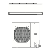
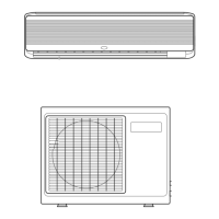
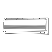
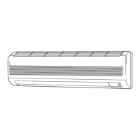
Detailed steps for installing the KS type wall-mounted indoor unit.
Instructions for installing and mounting the wireless remote control unit.
Steps for mounting the wireless remote control unit on a wall.
Specific instructions for wall mounting the wireless remote control for KS2432A.
Procedure for installing the optional wired remote control unit.
Locating and understanding the address switches on the remote and indoor units.
Setting switch positions for controlling two units or groups independently.
Steps to remove the protective spacer from the outdoor unit.
Procedures for securely installing the outdoor unit on its base.
Guidance on extending refrigerant tubing in various directions.
Essential safety and procedural guidelines for electrical wiring.
Specifications for power supply wire length and diameter.
Diagram illustrating the electrical connections between units.
Common wiring errors and their potential consequences for unit operation.
Detailed instructions for connecting wires to unit terminals.
Explanation of the flaring method for connecting refrigerant tubes.
Step-by-step guide for performing the flaring procedure with a flare tool.
Important precautions for ensuring tight and leak-free tube connections.
Safety measures and procedures to follow during brazing operations.
Instructions for connecting the refrigerant tubing between indoor and outdoor units.
Methods and materials for insulating refrigerant tubing to prevent condensation.
Guidance on taping refrigerant tubes and drain hoses together.
Final steps for sealing holes and completing the installation.
Procedure for purging air and moisture using a vacuum pump.
Steps to take before starting the air purging process.
Method for testing the system for refrigerant leaks.
Steps for evacuating the system to remove non-condensables.
Procedure for charging additional refrigerant based on tubing length.
Final steps after air purging, including valve cap replacement.
Checks and preparations required before conducting the test run.
Steps for operating the unit during the initial test run.
Procedure for performing a test run using the optional wired remote control.
Steps for collecting refrigerant gas for unit movement or servicing.