EasyManua.ls Logo

Sanyo SAP-KRV126EHDS - User Manual

Sanyo SAP-KRV126EHDS
148 pages
To Next Page IconTo Next Page
Loading...
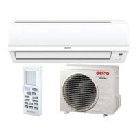
TECHNICAL & SERVICE MANUAL
OUTDOOR UNIT : SAP-CMRV1426EH
SAP-CMRV1926EH
SAP-CMRV1936EH
SAP-CMRV2446EH
SAP-CMRV3146EH
SAP-CMRV1426EH
SAP-CMRV3146EH
SAP-CMRV1926EH
SAP-CMRV1936EH
SAP-CMRV2446EH
DC INVERTER MULTI-SYSTEM AIR CONDITIONER
Outdoor Model No.
SAP-CMRV1426EH-F
SAP-CMRV1926EH-F
SAP-CMRV1936EH-F
SAP-CMRV2446EH-F
SAP-CMRV3146EH-F
Capacity
4.0kW
5.6kW
5.6kW
6.8kW
8.0kW
Product Code No.
1 852 355 43
1 852 355 44
1 852 355 45
1 852 355 46
1 852 355 47
REFERENCE NO. SM700846
< Applicable Indoor Units >
For details about the combination, refer to "Unit
Combination Table" in the Appendix of this manual.
NOTE
Wall mounted type
SAP-KRV96EHDSA
SAP-KRV126EHDS
SAP-KMRV76EH
SAP-KMRV96EH
SAP-KMRV126EH
SAP-KRV186EH
SAP-KRV246EH
Destination: Europe
RoHS
WARNING
This product does not contain any hazardous substances prohibited by the RoHS Directive.
• You are requested to use RoHS compliant parts for maintenance or repair.
• You are requested to use lead-free solder.
FILE NO.
Do not vent R410A into atmosphere : R410A is a fluorinated greenhouse gas,
covered by Kyoto Protocol, with a Global Warming Potential (GWP) = 1975.
F-GAS REGULATION (EC) No 842 / 2006

Table of Contents

Other manuals for Sanyo SAP-KRV126EHDS

Questions and Answers:

Sanyo SAP-KRV126EHDS Specifications

General IconGeneral
Cooling Capacity3.5 kW
Power Supply220-240V, 50Hz
Inverter TechnologyYes
TypeSplit
Star Rating3

Summary

Important Safety and Installation Guidelines

When Wiring

Safety guidelines for electrical wiring procedures in the outdoor unit.

When Transporting

Safe procedures for moving indoor and outdoor units to prevent injury.

When Installing

Guidelines for choosing installation locations and ensuring stability.

When Connecting Refrigerant Tubing

Procedures for connecting refrigerant tubing, including lubrication and tightening.

When Servicing

Safety precautions to take before performing maintenance or repairs.

Others

General safety notes regarding ventilation and refrigerant gas handling.

1. Operating Range

2. Specifications

2-1. Unit Specifications

Detailed specifications for outdoor unit models, including capacity and dimensions.

2-2. Major Component Specifications

Technical details of key components like compressor, fan motor, and heat exchanger coil.

2-3. Other Component Specifications

Specifications for sensors and other external components used in the outdoor unit.

3. Dimensional Data

4. Refrigerant Flow Diagram

4-1. Refrigerant Flow Diagram

Visual representation of the refrigerant path during cooling, heating, and defrost cycles.

5. Performance Data

5-1. Temperature Charts

Performance charts showing cooling and heating characteristics based on temperature.

6. Electrical Data

6-1. Electric Wiring Diagrams

Detailed wiring diagrams for outdoor units, showing component connections and terminals.

7. Functions

7-1. Explanation of Functions

Description of the operational modes and functions of the air conditioning system.

7-2. Protective Functions

Explanation of safety features and operational protection mechanisms built into the unit.

8. Troubleshooting

8-1. Precautions before Performing Inspection or Repair

Essential safety warnings and procedures before working on electronic components.

8-2. Trouble Diagnosis by Error Monitor Lamps

Guide to diagnosing issues using error lamps on the control circuit board.

8-3. Checking the Outdoor System

Procedures for checking the outdoor unit's operation and defrost function.

8-4. Trouble Diagnosis of Each Part

Table outlining common problems and corresponding inspection points for various unit parts.

8-5. Trouble Diagnosis of Fan Motor

Troubleshooting guide for common fan motor issues and diagnostic procedures.

9. Refrigerant R410 A: Special Precautions When Servicing Unit

9-1. Characteristics of New Refrigerant R410 A

Information on R410A refrigerant, its properties, and handling precautions.

9-2. Checklist before Servicing

Pre-service checklist including flare tool usage and oil types.

9-3. Tools Specifically for R410 A

List of specialized tools required for servicing R410A systems.

9-4. Tubing Installation Procedures

Guidelines for properly installing refrigerant tubing, including flare sealing.

9-5. In Case of Compressor Malfunction

Procedures for replacing a malfunctioning compressor and related checks.

9-6. In Case Refrigerant is Leaking

Steps for detecting, repairing, and recharging refrigerant after a leak.

9-7. Charging Additional Refrigerant

Instructions for adding refrigerant, especially when extending tubing length.

9-8. Retro-Fitting Existing Systems

Guidance on using R410A with existing systems and tubing.

Appendix A: Installation Instructions

1. General Information

1-1. Tools Required for Installation

List of necessary tools not included with the unit for installation.

1-2. Accessories Supplied with Unit

List of parts and accessories included in the unit package.

1-3. Optional Copper Tubing Kit

Information on optional kits for refrigerant tubing and fittings.

1-4. Type of Copper Tube and Insulation Material

Specifications for copper tubing and insulation materials required for installation.

1-5. Additional Materials Required for Installation

List of extra materials needed for proper installation, like tape and putty.

2. Installation Site Selection

2-1. Indoor Unit Location

Guidelines for selecting an appropriate location for the indoor unit.

2-2. Connecting Indoor Units

Instructions for connecting multiple indoor units to the outdoor unit.

2-3. Outdoor Unit Location

Recommendations for selecting a suitable and safe location for the outdoor unit.

2-4. Outdoor Unit Dimensions

Diagrams showing the external dimensions of various outdoor unit models.

2-5. Outdoor Unit Installation Diagram

Visual guide illustrating the layout and placement for outdoor unit installation.

3. Installation Process

3-1. Embedding Tubing and Wiring

Instructions for routing and securing refrigerant tubing and electrical wiring.

3-2. Drain Cap and Drain Elbow

Details on installing drain components for the outdoor unit.

3-3. Using the Flaring Method

Explanation of the flaring technique used for connecting refrigerant tubes.

3-4. Flaring Procedure with Flare Tool

Step-by-step guide on how to perform the flaring process correctly.

3-5. Caution Before Connecting Tubes Tightly

Important warnings and tips for securely connecting refrigerant tubes to prevent leaks.

3-6. Tubing Connections

Procedures for making temporary and final connections of tubing, including torque.

3-7. Refrigerant Tubing Insulation

Requirements for insulating refrigerant tubes to prevent heat loss and condensation.

3-8. Taping the Tubes

Instructions on how to tape refrigerant tubes and wiring bundles securely.

3-9. Finishing the Installation

Final steps for sealing the installation site after tubing is completed.

4. Air Purging

Air Purging with Vacuum Pump (Test Run)

Procedure for removing air and moisture from the refrigerant system using a vacuum pump.

Pump Down Procedure

Steps for recovering refrigerant gas from the system for relocation or disposal.

5. Wiring Instructions

5-1. General Precautions on Wiring

Essential safety and procedural guidelines for electrical wiring.

5-2. Recommended Wire Length and Diameter

Guidance on selecting appropriate wire sizes and lengths based on local codes.

5-3. Wiring System Diagram

Diagrams illustrating the electrical connections between indoor and outdoor units.

5-4. How to Connect Wiring to Terminal

Detailed instructions on preparing and connecting wires to terminal plates.

5-5. Wiring Instructions for Outdoor Unit

Specific wiring procedures for the outdoor unit, including grounding and cable management.

6. Test Run

7. Connecting a Home Automation Device

8. Installation Check Sheet

9. Electric Wiring Diagram

Appendix A: Installation Instructions

Appendix B: Installation Instructions

Appendix C: Unit Combination Tables

2-Room Outdoor Unit Combination Table

3-Room Outdoor Unit Combination Table

4-Room Outdoor Unit Combination Table

Meaning of Abbreviations

Related product manuals