Do you have a question about the Sanyo SAP-KRV94EHDX and is the answer not in the manual?
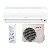
Detailed technical specifications for indoor and outdoor units.
Lists key components and their technical details for indoor and outdoor units.
Specifies resistance characteristics for various sensors used in the unit.
Shows the path of refrigerant through the system and insulation needs.
Displays cooling and heating performance curves based on temperature.
Illustrates air throw distances for cooling and heating under various conditions.
Lists electrical ratings, running current, and power input for different operating modes.
Provides comprehensive wiring diagrams and an abbreviation key for system connections.
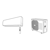
Advises on choosing optimal locations for indoor and outdoor units to ensure performance.
Specifies wire sizing and length limits for power and control wiring.
Provides guidelines on where to install the remote control unit for optimal operation.
Details the procedure for conducting a test run after installation.
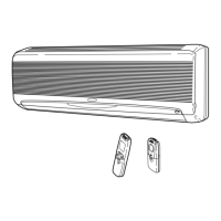
Step-by-step instructions for removing and reinstalling the indoor unit's front grille.
Explains how to set or change the remote control's address to prevent interference.
Instructions for detaching and reattaching the unit's drain hose.
Guides on removing the electrical component box and its related parts.
Steps for removing the panel motor, often related to flap movement.
Instructions for removing and reinstalling the drain pan assembly.
Details on how to remove the negative ion generator from the unit.
Step-by-step guide for removing and installing the fan motor.
Instructions on how to detach the fan from the unit.
Explains the procedure for safely disconnecting and reconnecting electrical connectors.
Details features like Emergency Operation, AUTO mode, and SENSOR DRY.
Explains the unit's built-in protective mechanisms like overload and freeze prevention.
Essential safety precautions to follow before starting any inspection or repair work.
Outlines how to initiate and interpret the unit's self-diagnostic modes.
Describes checks for indoor and outdoor units, including serial communications.
Guides on diagnosing issues related to the indoor and outdoor fan motors.
Discusses potential noise issues and electromagnetic interference problems.
Provides steps to check and resolve issues with the front panel's operation.
Steps for diagnosing problems specifically with the panel motor.
Details how to measure insulation resistance for various parts of the unit.
Explains how to check the continuity of the fuse on the PCB assembly.
Describes the composition and properties of R410A refrigerant.
A checklist of items to verify before commencing service on R410A systems.
Lists specialized tools required for servicing R410A refrigerant systems.
Provides guidance on proper tubing installation techniques and precautions.
Outlines the procedure for diagnosing and replacing a malfunctioning compressor.
Details the process for detecting, repairing, and recharging refrigerant after a leak.
Instructions for adding refrigerant, especially when extending tubing.
Advice on using existing units and tubing when converting to R410A.
Details how the unit automatically switches between cooling and heating modes.
Step-by-step guide for manually setting modes, temperature, and fan speed.
Instructions for setting fan speed automatically or manually.
How to operate the unit for air circulation without temperature control.
Explains the energy-saving night setback feature for cooling and heating.
Describes how to activate quiet mode to reduce fan noise.
Details the high power mode for increased cooling/heating output for 30 minutes.
Explains the function of generating negative ions to freshen room air.
Describes the UV anti-bacterial cleaning function activated by LED CLEAN mode.
Instructions for removing and cleaning the anti-mold filter.
Instructions for installing and cleaning the air clean filter.
Instructions for cleaning the negative ion generator.
| Brand | Sanyo |
|---|---|
| Model | SAP-KRV94EHDX |
| Category | Air Conditioner |
| Language | English |