Separately sold parts
F - 2
1. Parts for the outdoor unit
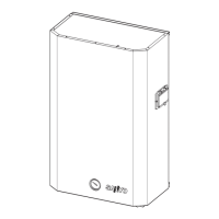
Component A Component B
Exhaust gas top
warning mark (red line)
Screw
(2 including
the opposite side)
Alignment mark
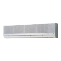
Component A
Existing exhaust gas pipe
Exhaust gas pipe fixing screws (2)
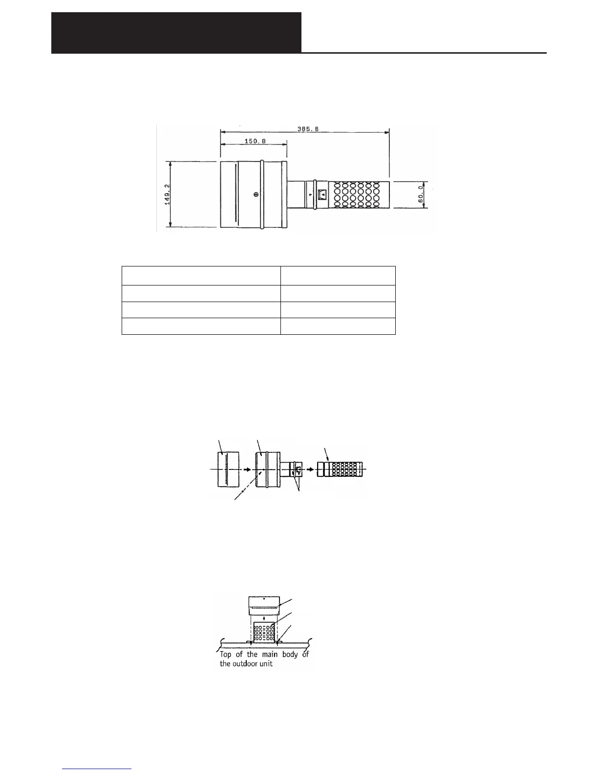
(1) Exhaust extension kit
1External dimension diagram
●Exhaust extension kit (SGP-PEX224F)
2Limitations when the exhaust pipe is extended
The following limits must be observed when carrying out exhaust pipe extension work.
* For exhaust pipe, use product name ONJ pipe φ60 series. This item to be supplied on site,
together with fittings (feet, split-halves) (supplier: Hokuai Corporation).
3Installing separately sold items
● Exhaust extension kit (SGP-PEX224F)
1) Remove the polythene bag from the adaptor for the exhaust gas extension, and verify each component.
2) Use a seal material. The seal material is to be supplied on site. Use Shinetsu Chemicals RTV-KE45 or
equivalent.
7) Remove the two screws securing the existing exhaust gas pipe on the top of the outdoor unit.
8) Place component A on the top of the existing exhaust gas pipe. Apply some seal material to the tips of the
two screws removed above, and connect component A together with the existing exhaust gas pipe on the top
of the main body.
3) Check that the alignment marks on component B are aligned. Pull the exhaust top in the direction of the
arrow.
4) Remove the two screws securing components A and B.
5) These screws will be used again for reassembly, so do not lose them.
6) Pull component B away from component A in the direction of the arrow.
Limitations during construction Limiting value
Outdoor air temperature -5
o
C or higher
Extension of the exhaust pipe 5m and 4 bends or less
Slope of the exhaust pipe Greater than 3/100 (upward)