5. ELECTRICAL ADJUSTMENT
1. CAMERA BLOCK ADJUSTMENT
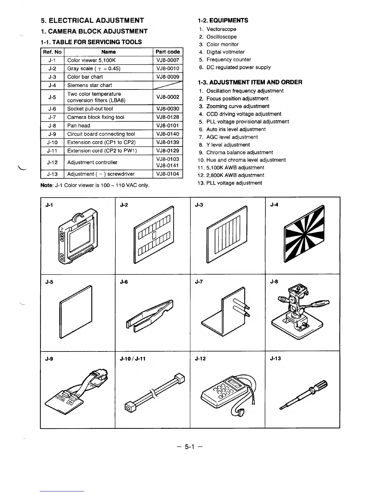
1-1. TABLE FOR SERVICING TOOLS
Ref. No
Name
J-1 Color viewer 5,1 00K
I J-2 lGrayscale(7 =0.45)
J-3 Color bar chart
J-4
Siemens star chart
J-5
Two color temperature
conversion filters (LBA8)
J-6 Socket ~ull-out tool
1 J-7 I Camera block fixing tool
I J-8 I Pan head
! J-9 I Circuit board connecting tool
J-1 O
Extension cord (CP1 to CP2)
J-1 1
Extension cord (CP2 to PW1 )
J-1 2
Adjustment controller
L
J-1 3
Adjustment ( – ) screwdriver
Note: J-1 Color viewer is 100-110 VAC only.
Part code I
VJ8-0007
VJ8-001 o
VJ8-0009
VJ8-0002
VJ8-0030
VJ8-0128
VJ8-0101
VJ8-0140
VJ8-0139
VJ8-0129
VJ8-0103
VJ8-0141
VJ8-0104
1-2. EQUIPMENTS
1.
Vectorscope
2. Oscilloscope
3. Color monitor
4. Digital voltmeter
5. Frequency counter
6. DC regulated power supply
1-3. ADJUSTMENT ITEM AND ORDER
1.
2.
3.
4.
5.
6.
7.
8.
9.
Oscillation frequency adjustment
Focus position adjustment
Zooming curve adjustment
CCD driving voltage adjustment
PLL voltage provisional adjustment
Auto iris level adjustment
AGC level adjustment
Y level adjustment
Chroma balance adjustment
10. Hue and chroma level adjustment
11. 5,1 00K AWB adjustment
12. 2,800K AWB adjustment
13. PLL voltage adjustment
– 5-1 –
 Loading...