2009 Sargent & Greenleaf, Inc. Document 630-806
Revised 2/15/2010
Sargent & Greenleaf, Inc. Sargent & Greenleaf S.A.
A Wholly Owned Subsidiary of Stanley Security Solutions, Inc. 9, chemin du Croset
PO Box 930, Nicholasville, KY 40356 1024 Ecublens, Switzerland
Phone: (800)-826-7652 Fax: (800)-634-4843 Phone: +41-21 694 34 00
Phone: (859)-885-9411 Fax: (859)-887-2057 Fax: +41-21 694 34 09
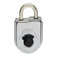
Installation Instructions for Model 2006 Pivot Bolt Electronic Safe Lock
The Model 2006 Pivot Bolt lock is a reversible, non-handed electronic safe lock. It will be necessary to plug the provided cable into the lock. This is a
phone-type connector that will only insert one way (Figure A). Make sure it is fully inserted and locked into the lock case receptacle. Either side of the
lock case can be mounted against the safe door to accommodate the direction of movement of the blocking bar or cam plate of the safe’s boltwork.
No matter which side of the case is placed against the safe’s mounting plate, the lock cable needs to be routed in the recessed channel in the lock’s
cover. Figure B shows the proper cable placement if the side opposite the cover is to be placed against the mounting plate. In this case, the cable
runs through the opening of the case and on through the safe’s spindle hole to the keypad. Figure C shows the proper cable placement if the cover
side of the lock is to be placed against the mounting surface. The cable is routed around the end of the lock case and through the recessed channel
where it will make a 90-degree bend before running through the safe’s spindle hole to the keypad. It is very important to make sure the cable is in the
recessed channel before the lock is tightened against the mounting surface.
1. The mounting surface should be smooth and
flat, with either ¼-20 or M6 mounting screw
holes. The wire channel (spindle hole) through
the safe door must be at least .312 inch
( 7,9 mm) in diameter. Insert the lock cable
through the spindle hole and gently pull it from
the front of the safe as you place the lock body
against the mounting surface.
2. After making sure the cable is protected within
the lock’s recessed channel and not crimped or
stressed at any point, attach the lock body to the
mounting surface using the screws provided.
Tighten the mounting screws to 30 to 40 inch-
pounds (33.9 to 45.2 dNm).
3. Make sure there is a minimum clearance of
0.150 inch (3.8 mm) between the end of the lock
case and the blocking bar of the safe’s boltwork.
4. If the safe incorporates a relock device plate,
it will likely attach to the lock body as shown. If it
attaches using the lock’s cover screw, make
sure the screws engage the lock by at least four
threads. Substitute longer 8-32 machine screws
if necessary. It may be necessary to trim longer
screws to a proper working length. Relock
device attaching screws must NOT be longer
than the depth of the tapped hole provided in
the lock case.
5. The lock cannot function properly if it binds
against the safe’s boltwork. This photo shows
boltwork in the fully locked position, placing
pressure on the side of the lock bolt. It could
prevent the lock from opening.
6. In this photo, the boltwork bind has been
relieved by removing a small amount of material
from the right side of the blocking bar’s bolt
opening. Now when the boltwork is fully thrown
to the locked position, there is air space on all
sides of the lock’s bolt. This is the desired
relationship.