This document provides installation instructions for the SARGENT 7800 and 8200 Series Mortise Locks, specifically when used with Sectional Trim and V Series Indicators.
Function Description:
The SARGENT 7800 and 8200 Series Mortise Locks are designed for secure access control in various applications. These locks are compatible with sectional trim and V Series indicators, offering visual feedback on the lock's status (e.g., locked, unlocked, vacant, occupied). The system supports different indicator variants, including cylinder, thumbturn, coin turn, and blank/no input options, allowing for flexible configuration based on specific security and operational needs. The mortise lock body itself can be re-handed to match the door's hand and bevel, ensuring proper functionality and aesthetic alignment. The installation process involves preparing the door, installing the mortise lock body, preparing the door for the indicator, installing levers, mounting the indicator plate, assembling the indicator, installing the cylinder, and attaching the outside front trim. A functional check is crucial after installation to ensure all components operate correctly and the indicator displays the accurate status.
Important Technical Specifications:
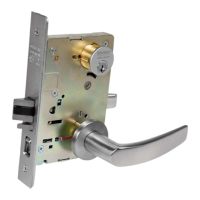
- Lock Series: SARGENT 7800 and 8200 Series Mortise Lock.
- Trim Compatibility: Sectional Trim.
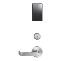
- Indicator Compatibility: V Series Indicators.
- Door Thickness: Standard 1-3/4" thickness for certain indicator spindle cams (81-0756*, 82-5577*). For other thicknesses, factory contact is required.
- Screw Types:
- Lock Screws: #12 x 1-1/4" wood screws or #12-24 x 1/2" machine screws (for temporary tightening).
- Lever Attachment: Two (2) #8-32 x 5/8" screws for securing the adapter and plate assembly; set screw for inside lever.
- Indicator Mounting Plate: Four (4) #6 x 3/8" sheet metal screws.
- Indicator Assembly: #8-32 x 5/8" screw for the top, #8-32 x 3/8" screw for the bottom (Torx security screws recommended).
- Outside Front Attachment: Two (2) flat head screws #8-32 x 1/4".
- Drill Bit Size: 3/32" diameter for indicator mounting holes.
- Cylinder Clamp Screw: Tightened with a #2 Phillips screwdriver.
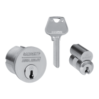
- Control Key: Removable Core or Interchangeable Core cylinders require a control key (stamped with C) for removal and installation. This is not standard and must be requested separately (specify 113511 cut for 1-bitted control key).
- Indicator Parts List:
- Sectional Escutcheon (Cylinder, Coin Turn, Thumbturn variants, No Input/Blank): Various part numbers depending on finish and type (e.g., 81-0742 x finish, 82-5635 x finish).
- Indicator Window: 81-0811.
- Indicator Display Assembly (Green Unlocked/Red Locked, Green Vacant/Red Occupied, Green Unlocked Icon/Red Locked Icon, White Unlocked/Red Locked, White Vacant/Red Occupied, White Unlocked Icon/Red Locked Icon): Various part numbers (e.g., 82-5602 to 82-5607).
- Indicator Spindle Cam (Thumbturn/Coin Turn, Cylinder/No Input/Blank, 05/37/38/59 Function): 81-0745, 81-0756*, 82-5577*.
- Indicator Retaining Pad: 81-0749.
- Sectional Indicator Screw Pack: 82-5590 x finish.
- Sectional Indicator Mounting Plate: 81-0750.
- Sectional Indicator Template Kit: 82-5601.
Usage Features:
- Indicator Variants: The system supports multiple indicator types (Cylinder, Thumbturn, Coin Turn, No Input/Blank) for diverse application requirements.
- Rehanding Capability: The indicator can be re-handed to match the door's specific hand (LH, LHRB, RH, RHRB) and bevel, ensuring correct orientation and operation. This involves adjusting the spindle cam position.
- Visual Status Feedback: V Series Indicators provide clear visual cues regarding the lock's status (e.g., "Locked," "Unlocked," "Vacant," "Occupied," or corresponding icons), enhancing user awareness and security.
- Multi-Function Lock Configuration: Instructions for setting the function of multi-function locks are referenced to the lock body instructions.
- Easy Installation: The installation process is detailed with step-by-step instructions and figures, making it manageable for installers.
- Retrofit Compatibility: The instructions advise ensuring a clean door surface when retrofitting over existing products to ensure the indicator sits flat.
- Security Screws: Torx security screws are recommended for indicator assembly for enhanced tamper resistance.
Maintenance Features:
- Functional Check: A crucial step after installation is to perform a functional check to verify that the key rotates freely, the key retracts the latch and deadbolt (if present), levers retract the latch and deadbolt, and the indicator displays the correct status. This helps identify and resolve issues early.
- Adjustability: The cylinder clamp screw allows for adjustment to ensure correct operation.
- Troubleshooting: If resistance is encountered during the functional check, the user is directed to refer back to the "Rehanding Indicator" section, suggesting that incorrect handing is a common issue that can be corrected.
- Component Replacement: The "Indicator Parts List" provides part numbers for individual components, facilitating easy identification and ordering of replacement parts if needed. This includes escutcheons, indicator windows, display assemblies, spindle cams, retaining pads, screw packs, mounting plates, and template kits.
- Cylinder Management: For removable or interchangeable core cylinders, the use of a control key is specified for core removal and installation, which is a standard maintenance procedure for these types of cylinders.