5
Synchronization
During data communication between the balance and a
connected device (computer), messages consisting
of ASCII characters are transmitted via the interface. For
error-free data communication, the parameters for baud
rate, parity, handshake mode and character format must
be the same for both units.
You can set these parameters in the Setup menu so that
they match those of the connected device. You can also
define parameters in the balance to make data
output dependent on various conditions. The conditions
that can be configured are listed in the descriptions of the
application programs.
If you do not connect a peripheral device to the interface
port, this will not generate an error message.
Handshake
The balance interface (Sartorius Balance Interface = SBI)
has transmit and receive buffers. You can define the hand-
shake parameter in the Setup menu:
-
Hardware Handshake (CTS/RTS)
-
Software Handshake (XON, XOFF)
Hardware Handshake
With a 4-wire interface, 1 more character can be transmitted
after CTS (Clear to Send).
Software Handshake
The software handshake is controlled via XON and XOFF.
When a device is switched on, XON must be transmitted
to enable any connected device to communicate.
Data Output by Print Command
The print command can be transmitted by PRINT or by
a software command (Esc P or Esc kP).
Automatic Data Output
Activate the “auto print” (Code 3.1.1.4., 3.1.1.5.) operating
code to have data output to the interface port without
a print command. You can have data output automatically
at defined display update intervals, with or without the
stability parameter. The length of a print interval depends
on the operating menu settings for AMBIENT (ambient
conditions) (menu code 1. 1. 1. x) and AUT.CYCL. (time-
dependent autom. printing; menu code 1. 6. 3. x). If you
activate the auto print setting, data will be transmitted
immediately the moment you turn on the balance.
In the operating menu, you can define whether automatic
printing can be stopped by pressing.
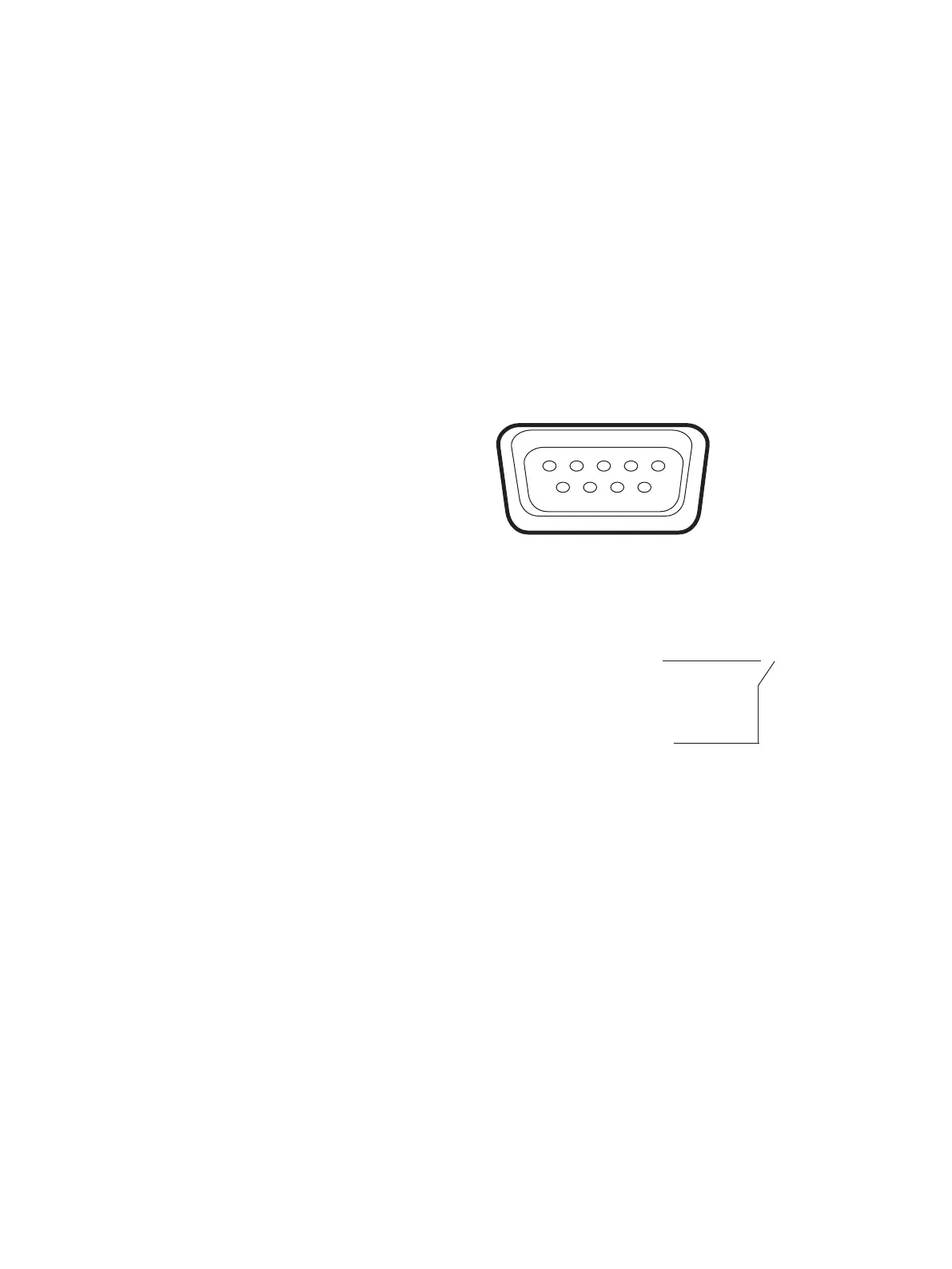
Pin Assignment Chart
Female Interface Connector:
Sub-D female connector 9-pin with screw lock hardware
Warning When Using Pre-wired RS232 Connecting Cable:
The pin assignments in RS-232 cables purchased from
other manufacturers may be incompatible with Sartorius
weighing instruments. Be sure to check the pin assignments
against the chart below before connecting the cable, and
disconnect any lines identified differently from those
specified by Sartorius. Failure to do so may
damage or even completely ruin your balance and/or periph-
eral device(s).
Pin Assignments:
5
9
1
6
Pin 1: Not assigned
Pin 2: Data output (T × D)
Pin 3: Data input (R × D)
Pin 4: Not assigned
Pin 5: Internal ground
Pin 6: Not assigned
Pin 7: Clear to Send (CTS)
Pin 8: Request to Send (RTS)
Pin 9: Universal key
 Loading...