10
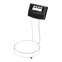
Replacing the Display PCB
The display PCB must be replaced if:
– the display is defective
– data output is defective
When replacing the display PCB, replace the cable connecting the display
PCB to the main PCB at the same time.
– Open the scale (see page 9)
– Remove or cut the wire tie holding the cable that connects the electronics
module to the display and control unit
– Now the display head together with the suport arm can be removed
– Carefully remove the protective cap (A) using a proper tool
– Push the pin out of the support arm
– Now the defective display head together with the connecting cable can
be removed
– Follow the above instructions in reverse order to install the new PCB
Replacing the Strain-Gauge Load Cell
– Open the scale (see page 9)
– Unplug the load-cell cable from the main PCB
– Remove the two screws from the pan support and put it aside
– Remove the three screws that tighten the strain gauge load cell from the
underneath. now the defective strain gauge load cell can be removed.
– Place the new strain gauge load cell in the housing adjust its position and
tighten it again.
– Tighten the pan support again.
– Guide the connecting cable into the electronics module and plug the
cable into the main PCB
– Now the zero-point offset value the lineaity and the span need to be
checked / adjusted.
Kopf-01d.TIF
 Loading...