Table 2-1 Read Request Block
Table 2-2 Write Request Block
32-bit integers occupy two
16-bit words – most
significant first
Table 2-3 Request Control
01=Read
10=Write
11=Clear
“Clear” and “No operation” remove the last
master command sent and clear the CANopen
input buffer. After the device restarts, “Write”
commands are ignored until “Clear” or “Read” is
sent first for device synchronization.
32-bit integers occupy two 16-bit words – most
significant first
Only applied to 16-bit analog registers. Will not
affect binary registers and counters.
Toggle the bit to synchronize a response
Defines the number of words in the data block
Note: Bit 0 is a least significant bit (LSB).
The following table describes the mapping between RPDOs and data bytes received by the
EM133:
Table 2-4 RPDO-EM133 Received Data Bytes Mapping
0x200 + Node ID (e.g. 0x027E for Node ID = 126)
0x300 + Node ID (e.g. 0x037E for Node ID = 126)
0x400 + Node ID (e.g. 0x047E for Node ID = 126)
0x500 + Node ID (e.g. 0x057E for Node ID = 126)
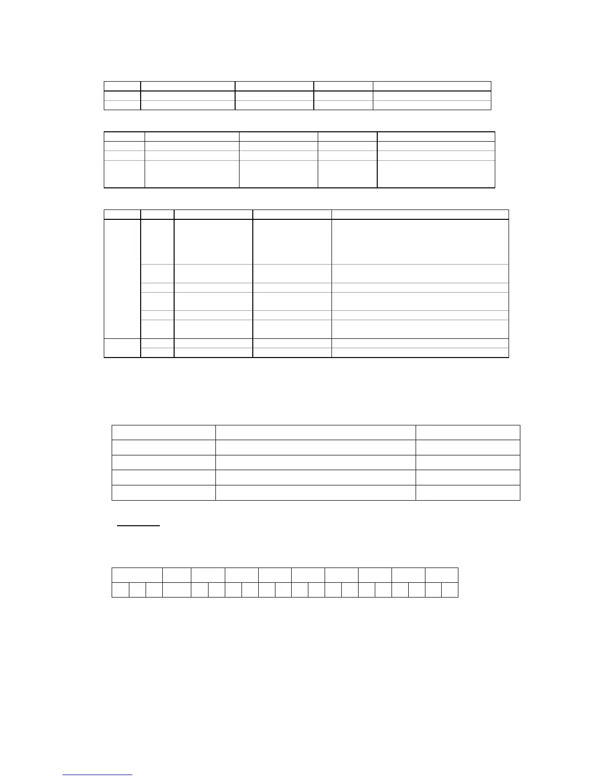
Example:
In order to read seven data points in a double word format (32 bits), i.e. 14 words,
starting with point 0x0C00 (V1-V3, I1-I3, kW L1, see section 3.1 below), from EM133
with CANopen Node ID = 126, the CANopen master writes a request as follows:
The first byte (Byte 1) contains a READ command (0x01), the second byte requests
reading of 14 words (0x0E), and bytes 3 and 4 specify the start point address of 0x0C00.
The CANopen master can request the EM133 to transmit TPDO1÷TPDO4 that contains the
data it needs by sending an empty TPDOs with the RTR flag.
 Loading...


