CONTROL PANEL INSTALLATION
23
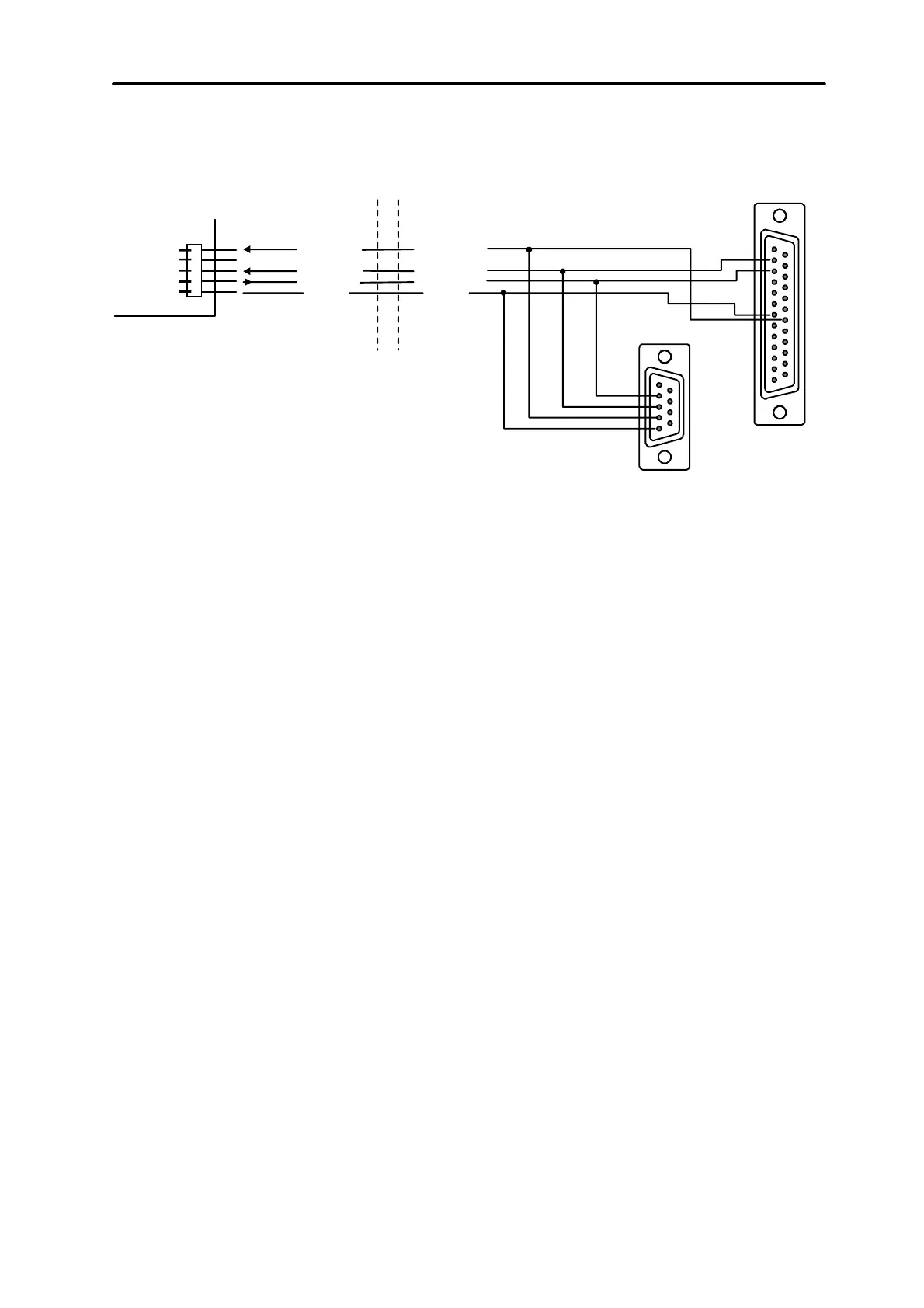
keypad cannot exceed 100 metres. Keypad connector signals are shown in Figure
14.
DSR keyp.
RXD keyp.
DTR comp.
TXD comp.
RXD comp.TXDkeyp.
COM
GND
KEYPAD
COMPUTER
SERIAL PORT
RS-232
2
3
7
20
2
3
4
5
Fig. 14. Connection of the computer to the LCD keypad RS-232 port.
NOTE:
Switch on the “RS communication” option in parameters of keypads, to which
user’s personal computer is to be connected. Data exchange with the computer starts
automatically, when the Guard64 program is started.
Each LCD keypad contains individual set of parameters, which determine its way of
operation in the system. These are:
• “Operated partitions...” – partitions, which can be armed/disarmed or alarm may
be cancelled from the keypad. Control will be possible for those users, who have
access to partitions specified here. When any partitions specified here is armed,
the keypad LED ARMED blinks. When all partitions specified here are armed, this
LED lights steadily.
• “Signals the alarms...” – list of partitions, for which a burglary alarm will be shown
in the keypad. Alarm will be indicated by LED ALARM and message at the display
will appear (when option “Alarm messages” – “partition” is on). Additional option
“Alarm signalling” determines whether an alarm is signalled audibly.
• “Signals GONG...” – list of zones, violation of which causes audible keypad alarm.
• „Quick Arm” – partitions, arming of which will be activated after typing 0# on the
keypad.
• “Tampering causes alarm...” – partition, in which an alarm occurs after tampering
of the keypad or when the keypad is disconnected from the system.
• “Alarm messages” – when an alarm occurs for the zone belonging to the partition
operated by the keypad, or other alarm in partition operated by the keypad takes
place, alarm message appears at the display.