CONTROL PANEL INSTALLATION
29
NOTES:
• Outputs OUT1..OUT4 are provided with a load presence detection unit, which is
active when output is not active. If a load is connected correctly and the control
panel indicates failure “No load present...”, connect a 2,2 k
Ω
resistor in parallel to
the load.
• When the signalling device connected to the output in parallel to the resistor 2,2 k
Ω
generates undesirable sounds, reduce value of resistance.
• Add 2,2 k
Ω
resistors to OUT1..OUT4 if these outputs are not used.
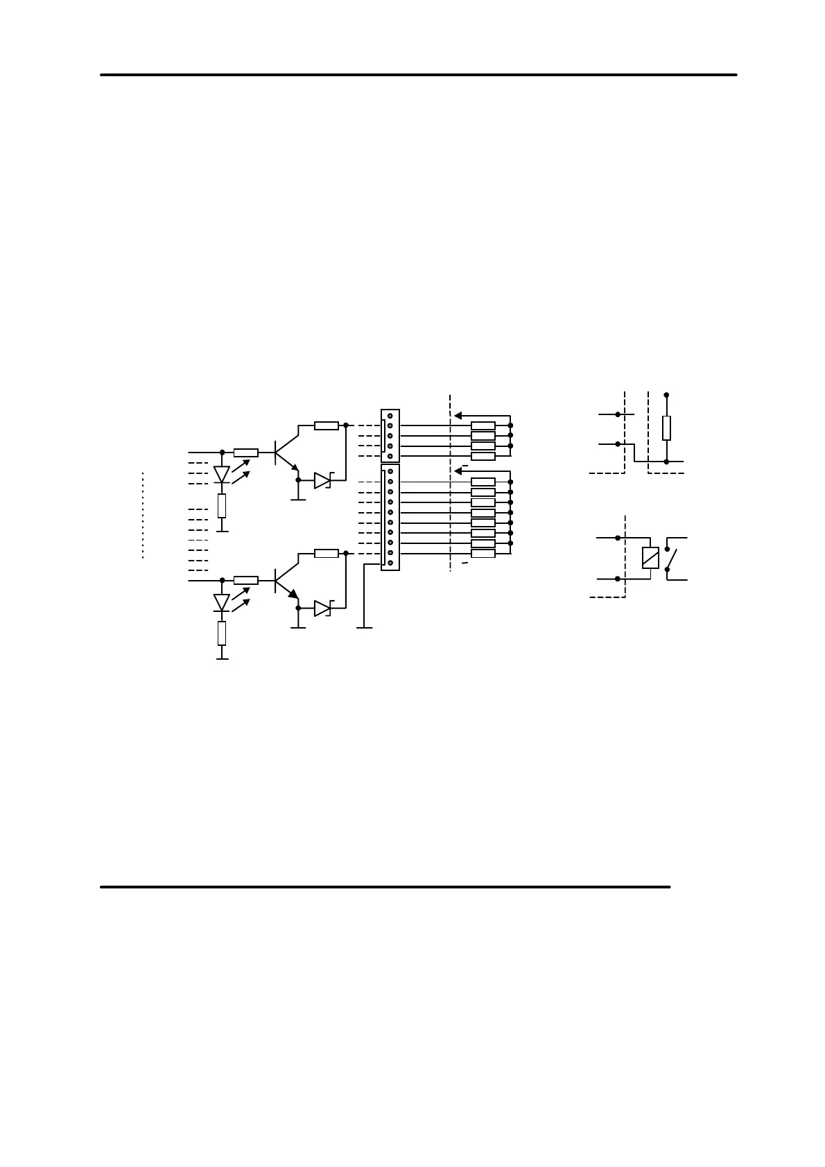
Remaining 12 control panel outputs are designed for control (for example, to control
signaller with their own power supply). Loads connected to these outputs (e.g. relays)
cannot demand the current exceeding 50 mA. Structure of OUT5..OUT16 outputs
and their use are shown in Figure 21.
OUT 5
OUT 16
+13,6 V
OUT 5
OUT 6
OUT 7
OUT 8
OUT 11
OUT 10
OUT 9
OUT 12
OUT 13
OUT 14
OUT 15
OUT 16
+13,6 V
COM
LOAD
50 mA
POTENTIAL-FREE
+
+
+13,6V
R
OUT n
+ Ucc
+12V
P
OUT n
RELAY OUTPUT
OUTPUT
Fig. 21. Connection of loads to outputs OUT5..OUT16 and signals from these outputs
(e.g. to the radio transmitter).
NOTE:
Power supply at connectors J22 and J23 is connected to power supply
outputs for expanders at the control panel board. Therefore, it is not
recommended to connect to it equipment exposed to tampering (e.g.
signallers with their own power supply).
Connection of telephone line
If the system uses the control panel telephone communicator (for monitoring,
messaging or remote programming), it is necessary to bring the telephone line to the
control panel. Telephone line is plugged to the terminal located in upper right corner
of printed board. In order to ensure correct messaging, the control panel must be
connected directly to the telephone line (terminals marked TIP, RING), and all other
equipment (telephone set, fax) – downstream the control panel (terminals marked T-
1, R-1). Such connection allows the control panel to fully take over the telephone line
for the time of phoning, which prevents the possibility of the messaging function to be
blocked by picking up the handset. Additionally, the telephone sets connected behind
the control panel do not signal phone calls made by the control panel.