28
System description and installation
CA-64 SATEL
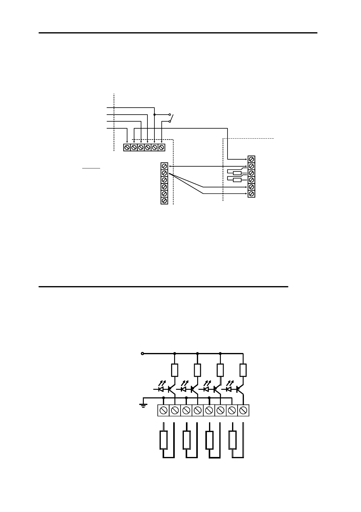
NO and NC detectors in a double-parameter configuration are connected in an
identical way, but it is important to inform the control panel which detector is
connected to the zone (2EOL/NO or 2EOL/NC).
+12 V
NO
C
TAMP
TAMP
GND
Z 8
COM
Z 7
Z 6
COM
Z 5
EKSPANDER
CONTROL
+12V DATACLKCOM
COM
CK n
DT n
+12 V
TMP
CAUTION!
DETECTOR POWER SUPPLY
GROUND AND SIGNAL GROUND
MUST USE SEPARATE WIRES
EXPANDER CASING
TAMPERING
DETECTOR
+12V
PANEL
Fig. 19. Connection of 2EOL detector to the expander for small distance between the
control panel and the expander (detector is located far from the expander).
NOTE:
Recommended power supply circuit for detectors connected to expanders is
shown in Figure 16 (point “Connection of expansion modules”).
Connection of signallers
Control panel CA-64 is provided with 16 outputs, application of which may be
programmed. In order to connect a signaller to the control panel, it is necessary to
program this output as an alarm output.
Four outputs are for high amperes with electronic circuit breaker set to 3A. The
structure of these outputs and the the way of connection to them signalling devices
without their own power supply (or without other loads) are shown in Figure 20.
COM OUT1 COM OUT2 COM OUT3 COM OUT4
LOAD
LED
FOR INDICATION
OF OUTPUT STATUS
LIMITERS
3A 3A 3A 3A
+13,6V
_
+
_
+
_
+
_
+
Fig. 20. Connection of a load (e.g. signaller) to outputs OUT1..OUT4.