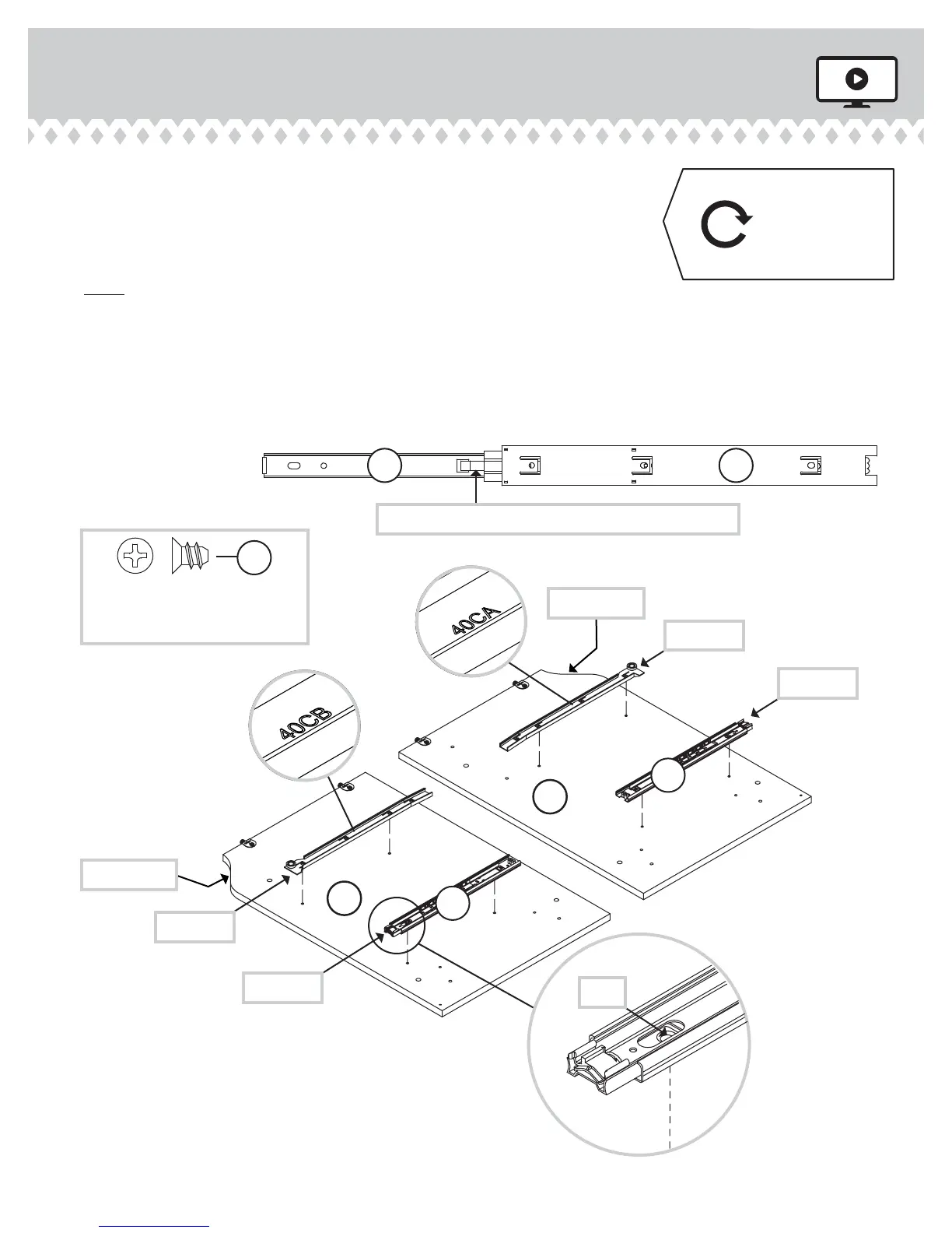
Step 2
å
Separate the EXTENSION SLIDES (Z) from the EXTENSION RAILS (Y) as
shown in the upper diagram below. Be prepared, the parts are greasy.
å
Fasten an EXTENSION RAIL (Y) to the LEFT END (B) and UPRIGHT (C). Use
four GOLD 5/16" FLAT HEAD SCREWS (QQ).
å
NOTE: For each EXTENSION RAIL, turn a SCREW into the hole shown in the
enlarged diagram. Then, slide the inner cartridge of the EXTENSION RAIL out
to fi nd the other hole that lines up with the hole in the END. Turn a SCREW
into this hole.
å
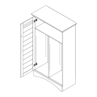
Fasten the CABINET RIGHT (40CA) and CABINET LEFT (40CB) to the LEFT
END (B) and UPRIGHT (C). Use four GOLD 5/16" FLAT HEAD SCREWS (QQ).
408761 www.sauder.com/servicesPage 6
C
B
Push the black lever in and pull the SLIDE from the RAIL.
Z Y
Curved edge
Open end
Curved edge
Open end
Remember:
Righty tighty.
Lefty loosey.
GOLD 5/16" FLAT HEAD SCREW
(8 used in this step)
QQ
Y
Y
Hole
1
2
3
4
1
2
3
4
Roller end
Roller end
Surface with
TWIST-LOCK®
FASTENERS
Surface with
TWIST-LOCK®
FASTENERS