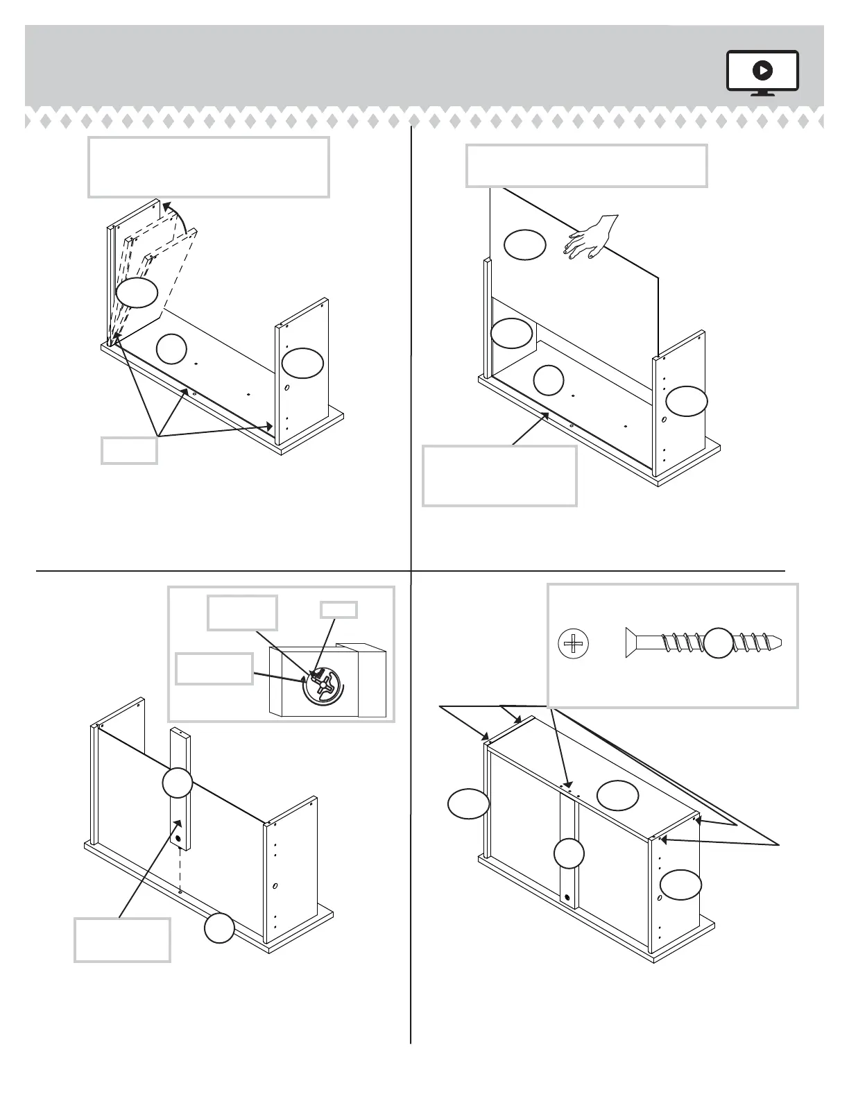
Step 13
415520 www.sauder.com/servicesPae 18
å
Insert the DRAWER SIDES (D30 and D31) at
an angle into the slot at each end of the
DRAWER FRONT (M).
å
Slide the DRAWER BOTTOM (D733) into the grooves
in the DRAWER SIDES (D30 and D31) and
DRAWER FRONT (M).
å
Fasten the DRAWER BRACE (Q) to the DRAWER
FRONT (M). Tighten one HIDDEN CAM.
å
Fasten the DRAWER BACK (D68) to the DRAWER
SIDES (D30 and D31) and DRAWER BRACE (Q). Use five
BLACK 1-9/16" FLAT HEAD SCREWS. (30S). Repeat this
step for the other DRAWERS.
The tabs should insert freely into the
slots. Gently tilt the DRAWER SIDES side
to side until the tabs slip into the slots.
UNFINISHED
Surface with
HIDDEN CAM
12
34
Be sure the DRAWER
BOTTOM inserts into the
DRAWER FRONT roove.
With the palm of your hand, tap the
DRAWER BOTTOM down into the roove.
Groove
Arrow
Maximum
210 derees
Minimum
190 derees
Start each screw a few turns before
completely tihtenin any of them.
BLACK 1-9/16" FLAT HEAD SCREW
(30 used in this step)
30S
Q
M
Q
VIEW THE T-LOCK BOX VIDEO
M
M
D31
D733
D68
D30
D30
D31
D31
D30