å
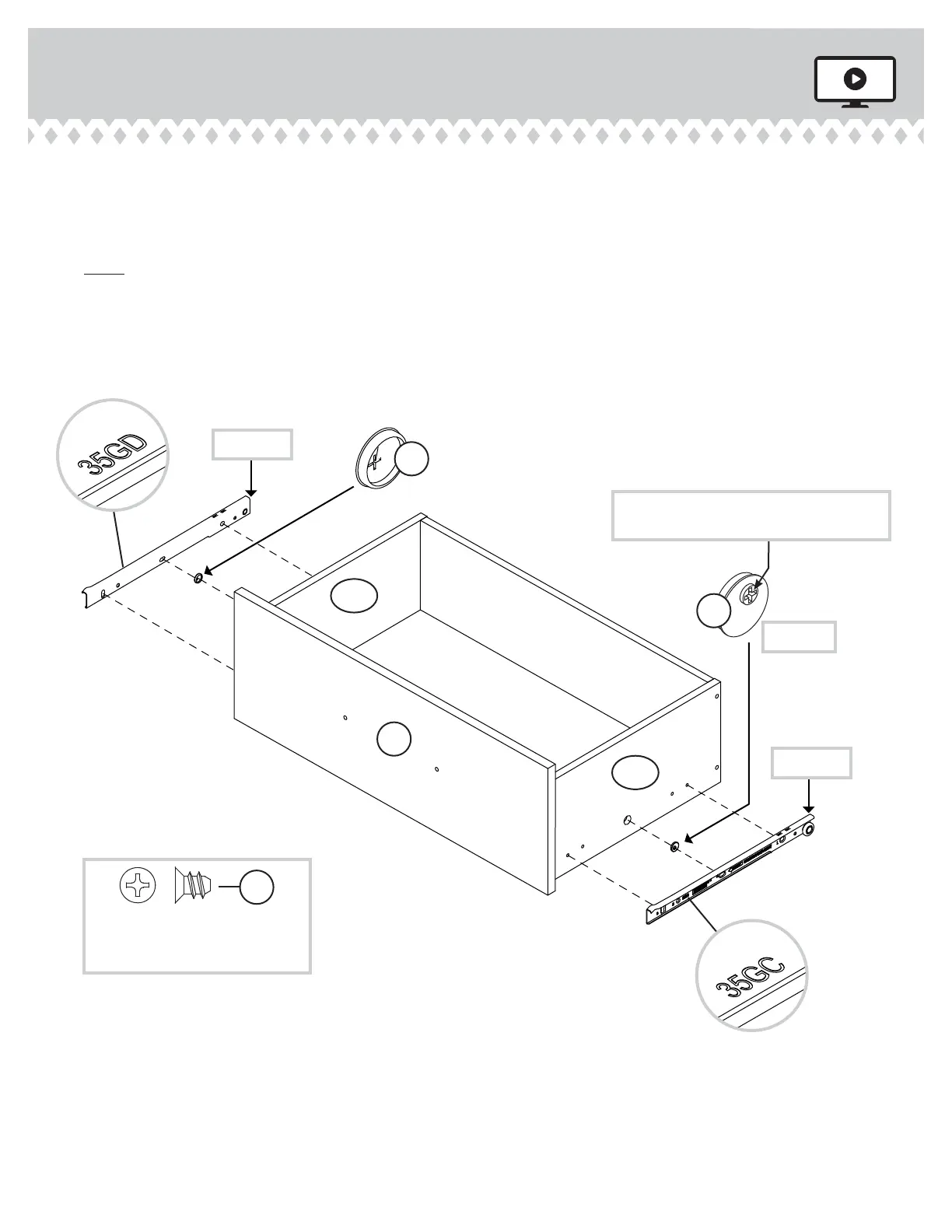
Insert a SLIDE CAM (10A) into the DRAWER SIDES (D30 and D31).
å
Fasten a DRAWER RIGHT (35GC) to the DRAWER RIGHT SIDE (D30) and a DRAWER LEFT (35GD) to the
DRAWER LEFT SIDE (D31). Use four GOLD 5/16" FLAT HEAD SCREWS (3S) throuh holes #1 and #3.
å
NOTE: The screw head in the CAM must be visible throuh the slotted hole in the SLIDE.
å
Repeat this step for the other DRAWERS.
Step 14
415520www.sauder.com/services
Pae 19
1
2
3
1
2
3
GOLD 5/16" FLAT HEAD SCREW
(24 used in this step)
3S
10A
10A
Screw head - turn CAM to line up holes in
the SLIDES with holes in DRAWER SIDES
Roller end
Roller end
(12 used)
M
D31
D30