Step
å
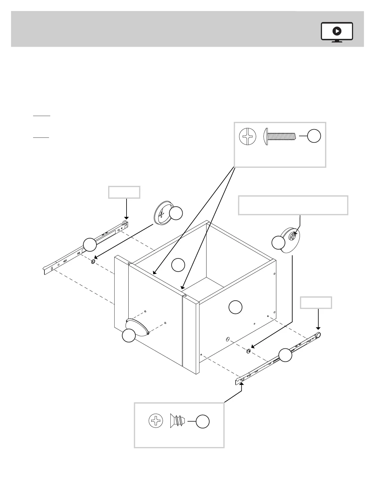
Insert a SLIDE CAM (10A) into each DRAWER SIDE (D28 and D29).
å
Fasten the SLIDES (II and JJ) to the DRAWER SIDES (D28 and D29).
Use four GOLD 5/16" FLAT HEAD SCREWS (3S) through
holes #1 and #3.
å
NOTE: The DRAWER SLIDES are marked "DRAWER RIGHT" and
"DRAWER LEFT" for easy identifi cation.
å
NOTE: The screw head in the CAM must be visible through the
slotted hole in the SLIDE.
å
Fasten a PULL (98K) to the DRAWER FRONT (N). Use two
SILVER 5/8" MACHINE SCREWS (15S).
Step 5
II
JJ
Screw head - turn CAM to line up holes in
the SLIDES with holes in DRAWER SIDES
1
2
3
10A
10A
1
2
3
Roller end
Roller end
D28
D29
GOLD 5/16" FLAT HEAD SCREW
(4 used in this step)
3S
(4 screws per drawer)
98K
SILVER 5/8" MACHINE SCREW
(2 used for the PULLS)
15S
417586 www.sauder.com/servicePage 10
 Loading...