5. Securely tighten the hexagon head screws crosswise. Observe the
tightening torque:
Ä
Chapter 3.2 ‘Requirements for maintenance work’
on page 9.
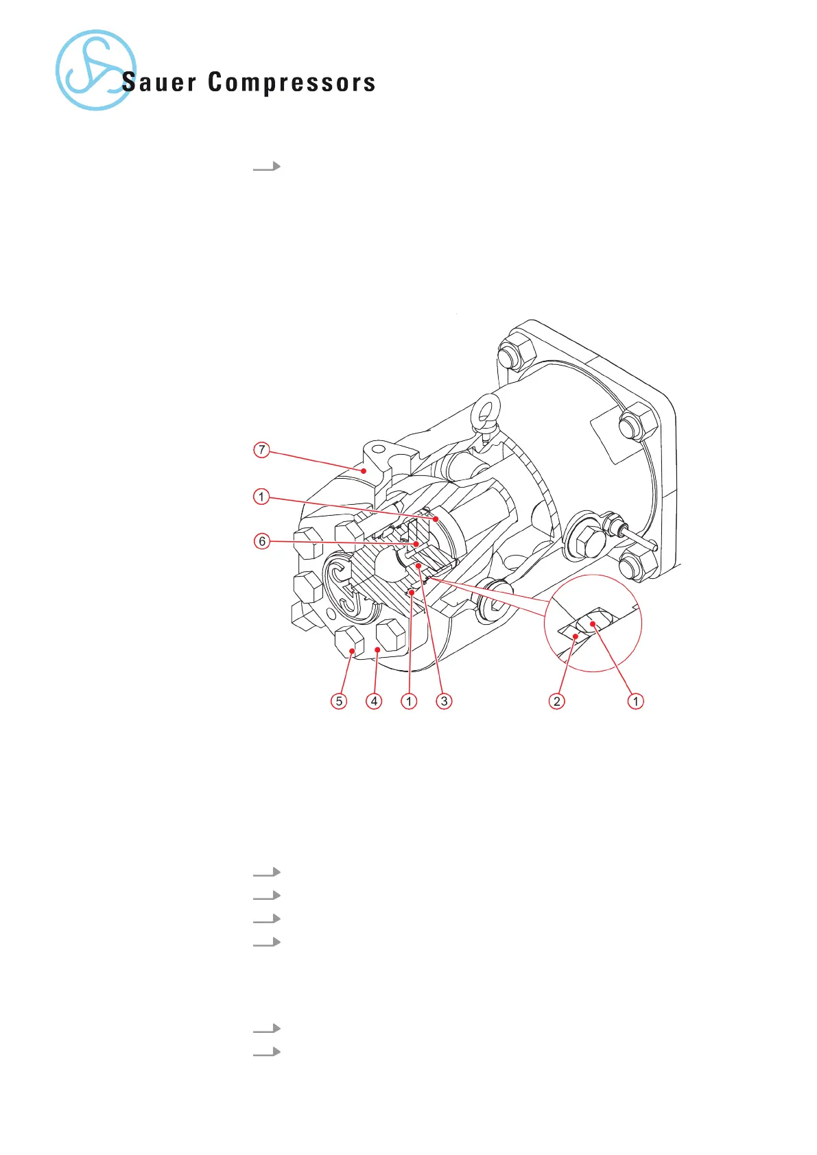
Fig. 9: Compression stage 4 valve
1 O-ring
2 Back-up ring
3 Ring gasket
4 Valve cover
5 Hexagon head screw
6 Valve
7 Cylinder
1. Unscrew the hexagon head screws and remove the valve cover.
2. Carefully remove the valve from the cylinder.
3. Remove the o-rings and gasket.
4. Clean all sealing surfaces.
1. Carefully insert the valve into the cylinder.
2. Fit a gasket between the valve and valve cover.
Removing the compres-
sion stage 4 valve
Installing the compres-
sion stage 4 valve
32 | WP5000 Basic WA 41013675 en GB 20190916