General system description 2 - 6
Doc.nr : 6611-018
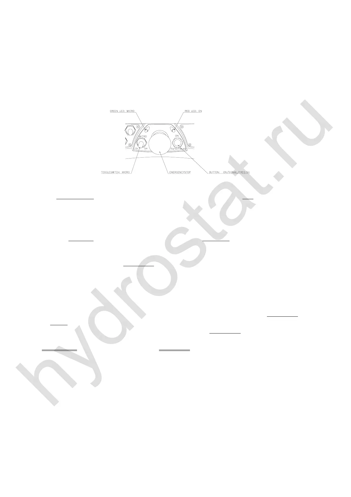
(PHUJHQF\VWRSSDQHO
There is a red emergency stop switch (
6723 ) with a manual twist reset, a push button
(
216,*1$/)5(46+,)7 ) and a red LED on the control unit’s emergency stop panel.
• The control unit is started with the sprung reset push button (216,*1$/)5(46+,)7 )
• A warning signal is produced on the crane ( 6,*1$/ ) by holding the push button down.
• All movement of the crane is stopped if the emergency stop is activated on the control
unit. The red LED indicates operating and battery status.
0LFUR6SHHGFRQWUROUHGXFWLRQRIVSHHG
This return sprung
switch can be used to reduce the operating speed in five ( 5 ) steps from
100% to 60%, 50%, 40%, 30% and 20% speed by limiting the hydraulic steering. The
regulation of the function’s speed is still made over the entire lever stroke and with retained
resolution.
• With impulses from the sprung loaded toggle switch to the left, WRZDUGV21, speed
reduction can be produced from 100% to 60%, 50%, 40%, 30% and 20% steering.
• Movement of the switch to the right, WRZDUGV2)), will produce 100% steering once
again ( See also next item ).
• For safety reasons, a return to 100% steering can only be made if all manoeuvre levers are
in their zero positions.
• When the green LED is blinking, the Micro-speed function is activated. The number of
blinks indicate the operating speed as defined below. If the emergency stop is pressed on
the controller unit, the controller unit will start from the last chosen speed.
*UHHQ/(' ,QGLFDWLRQ
Green LED not lit 0 to 100 % speed ( normal speed ).
1 blink every third second = 0 to 60 % speed
2 blink every third second = 0 to 50 % speed
3 blink every third second = 0 to 40 % speed
4 blink every third second = 0 to 30 % speed
5 blink every third second = 0 to 20 % speed

 Loading...