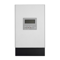
This document serves as a user manual for a 3KW Solar Charge Controller, providing comprehensive instructions for its assembly, installation, operation, and troubleshooting. It is crucial to read this manual thoroughly before any installation or operation to ensure safe and correct usage, and to keep it for future reference.
The solar charge controller is an advanced device designed to manage the charging of batteries from solar arrays. It incorporates intelligent Maximum Power Point Tracking (MPPT) technology, which significantly enhances efficiency by extracting the maximum possible power from solar panels. This technology allows the controller to continuously find and operate at the solar array's maximum power point, leading to an impressive efficiency increase of 25% to 30%.
Function Description:
The primary function of this solar charge controller is to efficiently charge batteries using solar power. It is compatible with various PV systems, supporting 12V, 24V, or 48V battery banks. The charging process is optimized for long battery life and improved system performance through a three-stage charging algorithm: Bulk, Absorption, and Float. This intelligent charging method ensures that batteries are charged effectively and maintained at optimal levels. The controller can handle a maximum charging current of up to 60A and boasts a maximum efficiency of 98%.
A key feature is the automatic battery voltage detection, which simplifies setup and ensures compatibility with different battery systems. It supports a wide range of lead-acid batteries, including wet, AGM, and gel types, making it versatile for various applications.
The device also includes robust self-diagnostics and electronic error protections. These features are critical for preventing damage to the unit and the overall system in case of installation errors or system faults, ensuring reliable and safe operation.
Usage Features:
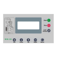
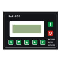
The solar charge controller is designed for ease of use and monitoring. It features a multifunctional LCD display that provides real-time information on the operating status and input/output power. The LCD shows critical data such as PV input voltage, battery voltage, charging power, and charging current. It also indicates the battery level through a series of bars, showing percentages from 0-24%, 25-49%, 50-74%, and 75-100%.
Operation is managed through a simple button interface. A short press can turn on the LCD backlight or change selections within menus. Pressing and holding the button for 5 seconds allows access to the setting mode, specifically for adjusting the charging current. The charging current can be set from 10A to 60A, with options C1 through C6 representing different current values. If no button is pressed for 5 seconds in the setting menu, the current settings are automatically saved, and the unit exits the setting mode.
For enhanced accuracy and system optimization, the controller includes a Remote Temperature Sensor (RTS) terminal. When an RTS is connected, it automatically provides temperature compensation for the charging process, which is crucial for prolonging battery life, especially in varying environmental conditions. The RTS cable can be routed with power wires, and there is no polarity requirement for its connection.
Another important usage feature is the Battery Voltage Sense connection. This allows the controller to precisely measure the battery terminal voltage, compensating for any voltage drop across the connection and cable resistance. This ensures that the charging algorithm operates based on the most accurate battery voltage, further optimizing battery performance and longevity.
The controller also offers various communication options. It comes with a default RS232 port, enabling connection to a PC for monitoring and firmware upgrades over short distances. Additionally, it features an integrated intelligent slot that supports different communication methods such as SNMP, USB, and MODBUS cards, providing flexibility for advanced system integration and remote monitoring.
Maintenance Features:
The manual emphasizes several safety and maintenance instructions to ensure the longevity and safe operation of the solar charge controller.
Safety First: Before any maintenance or cleaning, all wirings must be disconnected to reduce the risk of electric shock. The unit should not be disassembled by unqualified personnel; any service or repair must be performed by a qualified service center. It is explicitly stated that only qualified personnel should install this device with a battery.
Wiring and Grounding: Proper wiring is critical. The manual provides detailed instructions on power connections, including recommended wire sizes for different amperages and temperature ratings (75°C and 90°C wire types). Overcurrent protection, such as circuit breakers or fuses, must be installed in both battery and solar circuits, with specific ratings provided (e.g., 1.25 x 60 Amps = 75.0 Amps for the battery circuit). Disconnect switches are required for both battery and solar circuits to safely remove power from the charger.
The device must be connected to a permanent grounded wiring system, complying with local requirements and regulations. The grounding terminal is clearly identified with a ground symbol, and the minimum size for the copper grounding wire is specified as 8 AWG (10 mm²). A critical warning advises against bonding the system electrical negative to earth ground at the controller.
Polarity and Connections: Extreme caution is advised when connecting power wires to ensure correct polarity for both battery and solar connections. Incorrect polarity can lead to damage. Users are instructed to measure the voltage on open battery and solar wires before connecting them to the controller and to disconnect breakers/disconnects during wiring.
Temperature Management: The RTS is highly recommended for effective temperature-compensated charging. If the RTS is not used, the controller will not activate this function. Users are warned never to place the temperature sensor inside a battery cell, as this could damage both the RTS and the battery. Maintaining a cool environment for the charger is also recommended to prevent over-temperature faults.
Troubleshooting: The manual includes a comprehensive troubleshooting section that lists various fault codes and warning situations, along with their corresponding solutions. This allows users to diagnose and resolve common issues such as over-charge current, over-temperature, battery voltage too low or high, PV high loss, battery temperature too low or high, and no display on the LCD screen. Solutions range from restarting the charger and checking wire connections to verifying solar panel voltage and ambient temperature. If problems persist after following these steps, users are advised to contact their local dealer or service center for maintenance.
Environmental Considerations: The controller is designed for indoor applications with an IP31 rating. It should be mounted on a solid, non-flammable surface at eye level for easy LCD readability. Proper air circulation is essential for heat dissipation, with specified clearances (20 cm to the sides, 50 cm above and below). The optimal ambient temperature for operation is between 0°C and 55°C.
By adhering to these instructions and utilizing the provided features, users can ensure the safe, efficient, and long-lasting operation of their solar charge controller.