MAIN SPECIFICATIONS
4 5
PUTTING INTO SERVICE 1/2
FOR RIVNUTS
M3 TO M12
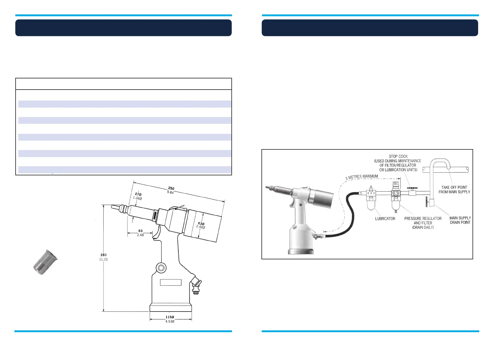
Dimensions shown in bold are millimetres.
Other dimensions are in inches.
Intent of use
Air supply
Tool dimensions
Tool specification
Air Pressure Minimum - Maximum 5-7 bar (75-100 lbf/in’)
Free Air Volume Required @ 5 bar/75 lbf/in’ 8 litres (0.28 ft
3
)
Stroke Maximum 7 mm (0.276 in)
Motor Speed Spin On 2,000 rpm
Spin Off 2,000 rpm
Pull Force @ 5 bar/75 lbf/in’ 19.1 kN (4,300 lbf)
Cycle Time Approximately 2.5 seconds
Noise Level Less than 75 dB(A)
Weight Without nose equipment 2.2 kg (4.85 lb)
Vibration Less than 2.5 m/s
2
(8 ft/s
2
)
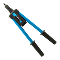
All tools are operated with compressed air at an optimum pressure of 5.5 bar. We recommend the use
of pressure regulators and automatic cooling/filtering systems on the main air supply. These should be
mounted within 3 metres of the tool (see diagram below) to ensure maximum tool life with minimum tool
maintenance.
The flexible hoses should have a minimum effective working pressure rating of 150% of the maximum
pressure produced in the system or 1O bar, whichever is the highest. Air hoses should be oil resistant,
have an abrasion resistant exterior and should be armoured where operating conditions may result in
hoses being damaged. All air hoses MUST have a minimum bore diameter of 6.4 millimetres or 1/4 inch.
Read servicing daily details in this manual.
The hydro-pneumatic tool is designed to place TOOL threaded inserts at high speed - making it ideal for
batch or flow-line assembly in a wide variety of applications throughout all industries.
A complete tool is made up of the base tool and the appropriate nose assembly for the insert.
Nose assemblies must be fitted as described in this manual.