PUTTING INTO SERVICE 2/2
6 7
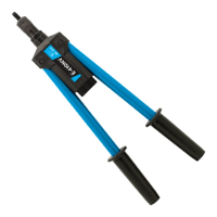
NOSE ASSEMBLIES
This adjustment is necessary to ensure optimum insert deformation. Is is suggested, therefore, that a test
plate with the same thickness and hole size as the workpiece be used.
If deformation is insufficient, the insert will rotate inside the application.
If deformation is excessive, thread distortion will occur and possibly drive screw fracture.
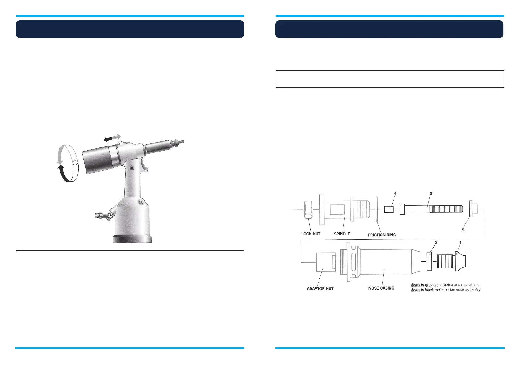
The stroke is adjusted by the amount the rear casing (86) is screwed in or out. To shorten stroke, screw in;
to lengthen stroke, unscrew the rear casing but never more than 5 turns from the fully ‘IN’ position unless
dismantling the tool. Adjust until optimum deformation is obtained.
Lock the stroke set finger (88) into the rear casing.
Stroke adjustment
Servicing Instructions
Fitting instructions
Operating procedure
- Connect the tool to the air supply.
- Offer up insert, lip first, to the drive screw. A slight pressure on the trigger will start the motor and
automatically thread the insert up against the nose and stop.
- Insert fastener squarely into application.
- Fully depress the trigger. This will both place the insert into the application and reverse it off the drive
screw.
Item numbers in bold refer to the General Assembly drawing and Parts List (pages 12-13).
It is essential that the correct nose assembly is fitted prior to operating the tool. By knowing the details of
the fastener to be placed, you will be able to order a new complete nose assembly if required.
IMPORTANT : The air supply must be disconnected when fitting or removing
nose assemblies unless specifically instructed otherwise.
Item numbers in bold refer to illustration below:
• If still fitted, remove the nose casing and the adaptor nut.
• Insert Drive Shaft 4 into spindle.
• Fit Drive Screw 3 onto Drive Shaft 4.
• Insert Reducing Sleeve 5 (if specified) into the adaptor nut.
• Screw the adaptor nut onto the spindle.
• Hold the spindle with a spanner* and tighten the adaptor nut clockwise.
• While holding the adaptor nut with the spanner*, tighten the lock nut anti-clockwise.
• Screw on the nose casing and Nose Tip 1 with the nose tip Lock Nut.
• The reverse operation is carried out for equipment removal.
• With tool still disconnected from air supply, screw one insert onto drive screw manually - making sure
the insert is flush with the end of the drive screw.
• Set nose tip in exact position and lock nose tip nut clockwise with a spanner*.
• Remove the insert from drive screw.
Nose assemblies should be serviced at weekly intervals.
• Remove the complete nose assembly using the reverse procedure to the ‘Fitting Instructions’.
• Any worn or damaged parts should be replaced with a new part.
• Particularly check wear on the Drive Screw
• Assemble according to fitting instructions (see above).