User Manual, Power contactors, series CT1115/08 and CT1130/08
Rev. 2.2 Page 16/26
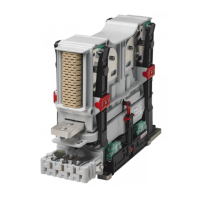
Electrical installation of
the auxiliary switches
Connect the wires for the auxiliary contacts. For the a1 and b0 contacts
(Switches S870) no polarity must be observed. For the general purpose
contacts (Snap action switches S826) the polarity must be observed. The
position of the switches and the terminal numbers are shown on a label on
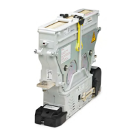
the protection cap. Bundle and fix the wires as shown below.
Fix the protection cap and tighten the knurled thumb screws. Secure the
nuts by hand force as tight as possible.
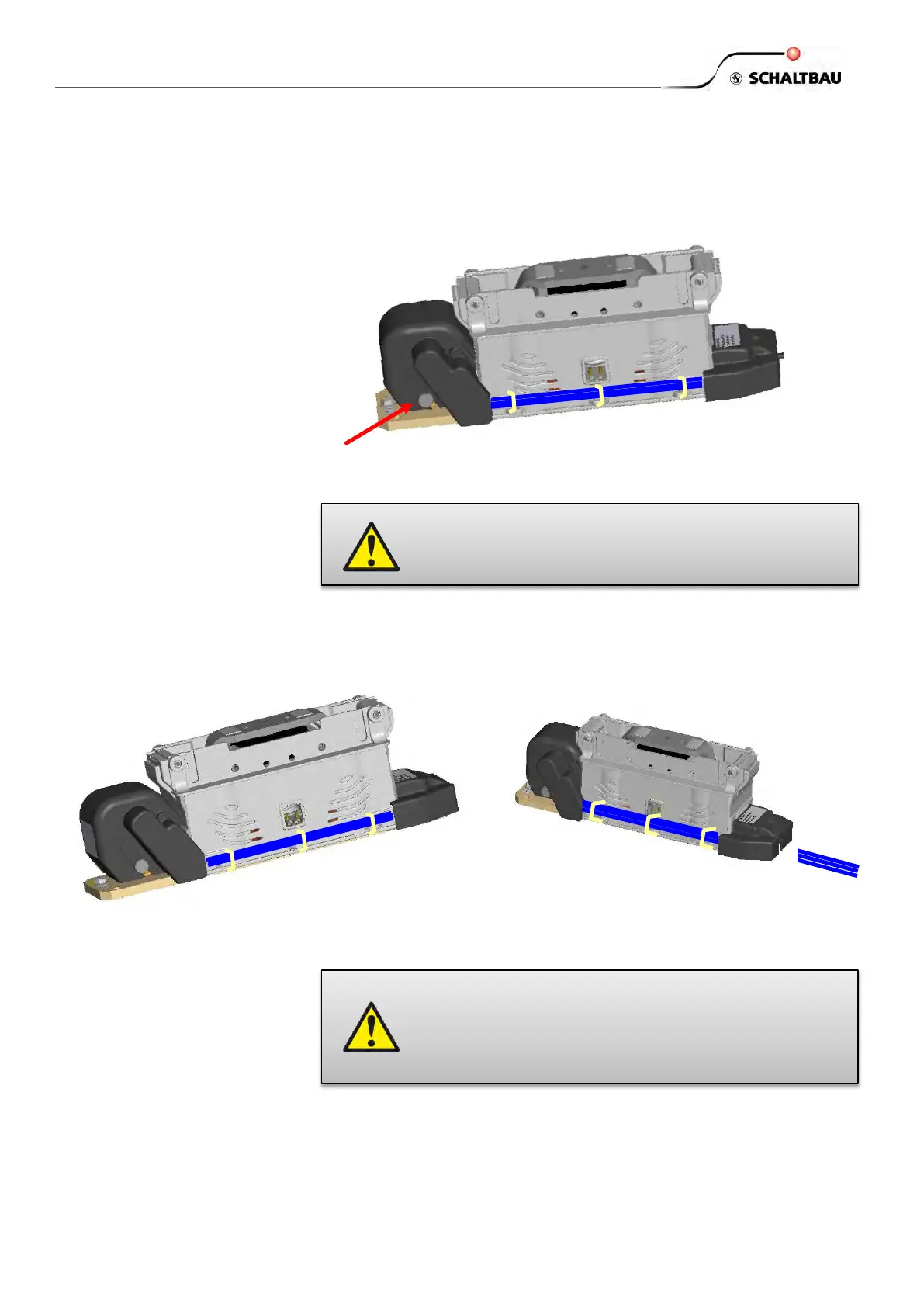
Electrical installation of
the magnetic drive
Connect the coil control wires to the cage clamp terminals. No polarity must
be observed. Bundle and fix the wires as shown below.
Fix the protection cap with the M4 x 10 screw.
The coil is protected against excessive overvoltages (which will occur when
the coil is switched off) by a bi-directional suppressor diode.
The protection cap for the auxiliary switches must not be
removed for operation. It is part of the insulation system.
Operation without the protection cap is not permissible.
The value of the overvoltage limitation is part of the
magnetic system and must not be changed or short-
circuited by external means. It is explicitly stated that the
use of diodes is prohibited for that purpose. Take care
there is no such diode in the external control circuit.
 Loading...