EasyManua.ls Logo

Schaltbau CT1115/08 Series User Manual

Schaltbau CT1115/08 Series
26 pages
To Next Page IconTo Next Page
Page #1 background imageLoading...
Page #1 background image
3
Inhalt
Rundsteckverbinder für Spezialanwendungen, Baureihe SB
2
Besondere Merkmale
2
Applikationen
2
Baureihenübersicht
2
Kompetenz
2
Normen
2
Technische Daten
3
Bestellschlüssel
4
5-polig + PE Flanschstecker, Kabeldose
4
6-polig Flanschdose, Kabelstecker
5
14-polig Flanschstecker, Kabeldose
5
Montage
6
Werkzeuge Ausdrückwerkzeuge AWZ-A und AWZ-C/H, Crimpzange CWZ-600
6
Montagebohrungen
6
Kontakte Stecker: Crimpkontakte, Dosen: Lötkontakte
7
Deratingkurven
7
Sicherheitshinweise
7
Contactors
Contactors
CT1115/08, CT1130/08 series
Single Pole NO
Power Contactors
for AC and DC
Manual C20/08-M.en
Question and Answer IconNeed help?

Do you have a question about the Schaltbau CT1115/08 Series and is the answer not in the manual?

Schaltbau CT1115/08 Series Specifications

General IconGeneral
SeriesCT1115/08
ManufacturerSchaltbau
Dielectric Strength2.5 kV
Mechanical Life10^7 operations
Electrical Life10^5 operations
WeightApprox. 0.2 kg
TypeRelay

Summary

Contactors

Conventions for this Manual

Introduction

Safety information

Electrical hazards

Details potential dangers from contact with live parts, stressing severe injury or death risk.

Safety notices

Highlights critical safety measures like not removing protection caps and using qualified personnel for service.

General application notes

Specifies operating environment, pollution degree, and potential magnetic field interference with external devices.

Technical data

Applied standards

Lists relevant railway application standards (EN 60077, EN 50124, EN 61373, EN 50125) for contactor specifications.

Description

Lower Module

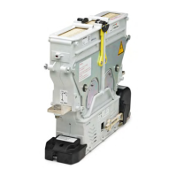
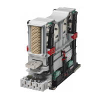
Describes the lower part of the contactor, including magnetic drive, base plate, and auxiliary contact group.

Upper Module

Details the upper part of the contactor, comprising fixed contacts, arc chamber, and latching levers.

Functional description

Order code

Storage

Return shipments

Recommends using original packaging for return shipments and ensuring adequate protection against damage.

Installation

Unpacking and handling

Provides instructions on inspecting packaging, unpacking the contactor, and separating the upper and lower modules.

Operating position

Mechanical requirements

Device dimensions

Refers to dimensioned drawings for specific device dimensions relevant to installation and mounting.

Installation dimensions

Directs users to dimensioned drawings for precise installation and mounting space requirements.

Electrical requirements

Mechanical installation

Electrical installation of the auxiliary switches

Electrical installation of the magnetic drive

Mounting of the Upper Module

Electrical installation of the main circuit

Electrical installation of the earth terminal

Commissioning

Maintenance

Recommended regular service intervals

Specifies checking intervals for optical inspection and main/auxiliary contacts based on operational usage.

Unscheduled service intervals

Defines conditions for carrying out extraordinary services due to fault conditions or high switching numbers.

Inspection activities

Details inspection procedures for high voltage supply cables, earthing, main contacts, and auxiliary contacts.

Spare parts, replacement of parts

Main contacts and ceramic protection insert

Identifies spare parts for main contacts and ceramic protection inserts and outlines their replacement procedure.

Remove and replace the fixed contacts (and ceramic protection insert)

Reassembly of the fixed contacts

Auxiliary contacts

Removal of the auxiliary switch subassembly

Details the process for removing the auxiliary switch subassembly, including unscrewing and pulling out the unit.

Reassembly of the switch subassembly

Related product manuals