User Manual, Power contactors, series CT1115/08 and CT1130/08
Rev. 2.2 Page 9/26
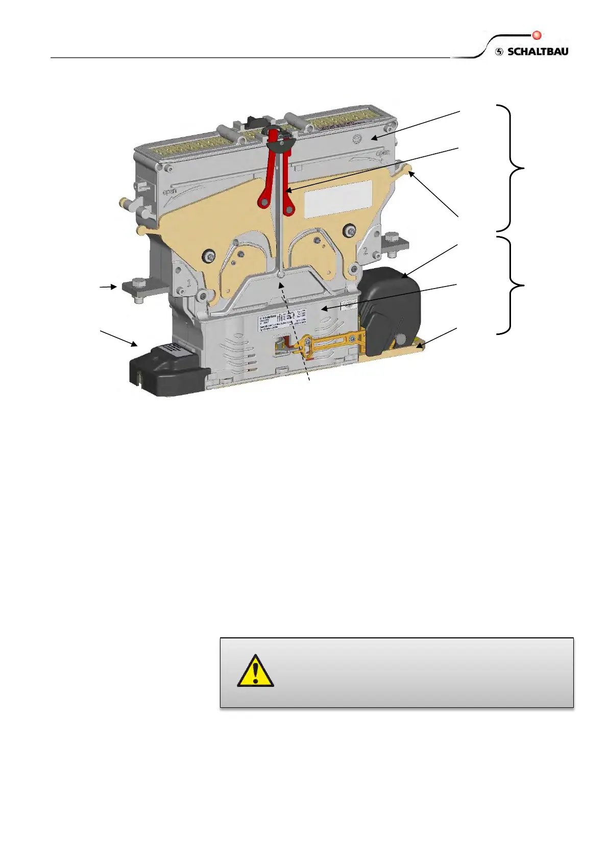
CT1000 contactors consist of two main modules:
Lower Module:
Magnetic drive (MD) with moving contact bridge (MC, not visible);
base plate (BP); auxiliary contact group (AG); coil terminal group
(TG); AG and TG are under protection caps.
Upper Module:
Fixed contacts with main terminals (FC); arc chamber (AC); latch-
ing levers (LL) and lock bars (LB)
Magnetic drive (MD) with moving contact bridge (MC)
- Compact magnetic drive system for DC voltages.
- Designed for standard railway supply voltages and tolerances.
Standard nominal supply voltages are U
s
= 24 V and U
s
= 110 V,
tolerances from 70% up to 125% of U
s
. Other nominal supply
voltages are available on request.
- Double-break moving contact bridge.
- Polarity independent overvoltage protection device.
Base plate (BP)
- 4 fixation holes
- Earthing terminal
The contactor should be mounted on a metal rack to provide a se-
cure mounting as well as a heat sink for the magnetic drive.
The value of the overvoltage limitation is part of the
magnetic system and must not be changed or short-
circuited by external means. It is explicitly stated that the
use of diodes is prohibited for that purpose. Take care
there is no such diode in the external control circuit.
 Loading...