4 Situation: 18.07.2005 SDT-0018-02EN
Instruction Manual Control and Switch Panel DT 201 B
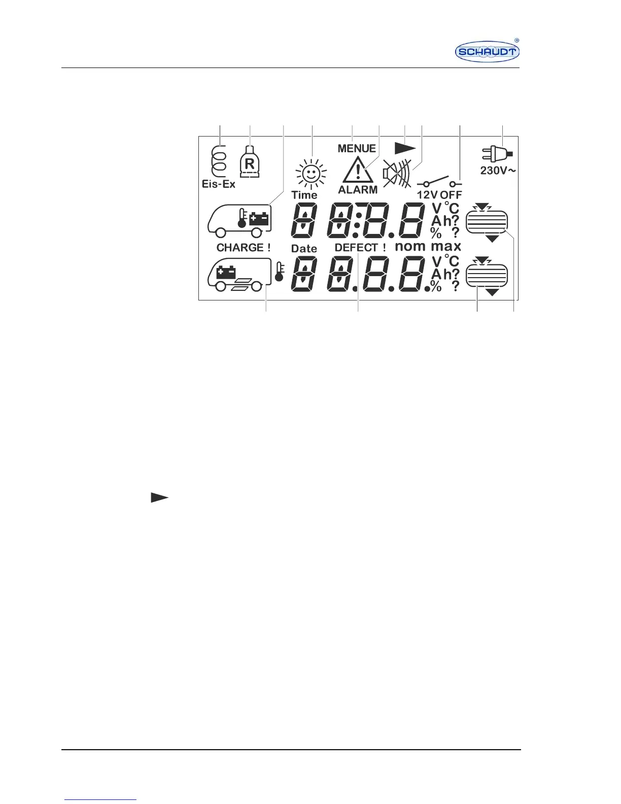
Symbols on the display Symbols, measured values and settings of the selected display are indicated
in the display window.
Fig. 2 Display window
1 Defroster switched on
2 Spare cylinder in use
3 Living area battery/inside temperature
4 Solar current
5 Setting menu
6 Battery and filling level alarm
7 Call up next page
8 Optical display for buzzer/warning that buzzer is switched off
9 12 V Off display (3 seconds)
10 230 V power supply is connected
11 Water tank
12 Waste water tank
13 Fault display for battery, filling level sensors, temperature sensors
14 Starter battery/outside temperature/step
Calling up the next page If the arrow is visible in the display window, the next page can be called up
with the basic display, tank, battery and menu buttons.
4 Technical data
Operating voltage 12 V (10 - 14.5 V), powered via Electrobloc
 Loading...