14 Situation: 17.06.2005 831.300 SDT-0060-00EN
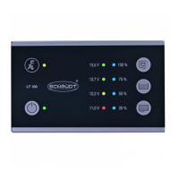
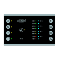
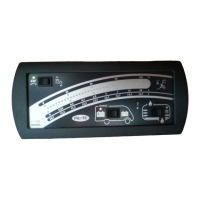
Instruction Manual Control and Switch Panel LT 500
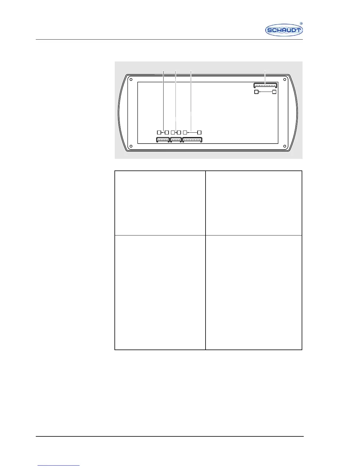
11 Circuit diagram - for specialist workshop only
Fig. 2 Circuit diagram for control and switch panel LT 500
615 1
12 1
110
X1
SDT00282
X2 X3 X4
Plug assignment for the
circuit diagram
X1 block 3 Lumberg 2.5 MSFQ/0
6 x to water tank
X2 block 4 Lumberg 2.5 MSFQ/0
5 x to waste water tank
1. Full 1. Full
2. 3/4 2. 3/4
3. 1/2 3. 1/2
4. 1/4 4. 1/4
5. Base water tank 5. Base waste water tank
6. Not assigned
X3 block 1 Lumberg 2.5 MSFQ/0
10 x
X4 block 2 Lumberg 2.5 MSFWQ/0
12 x to Electrobloc
1. D+ 1. Main switch relay 1 Off
2. Pump 2. Main switch relay 1 On
3. Waste water tank heater 3. Main switch relay 2 Off
4. Frost protection valve 4. Main switch relay 2 On
5. Not assigned 5. Mains signal
6. Not assigned 6. Shunt consumer
7. Not assigned 7. Shunt battery
8. Not assigned 8. Negative living area battery sensor
9. Not assigned 9. Not assigned
10. Not assigned 10. + Living area battery sensor
11. + Starter battery 12 V
12. + Lighting
 Loading...